723–0018 /02 F70 57
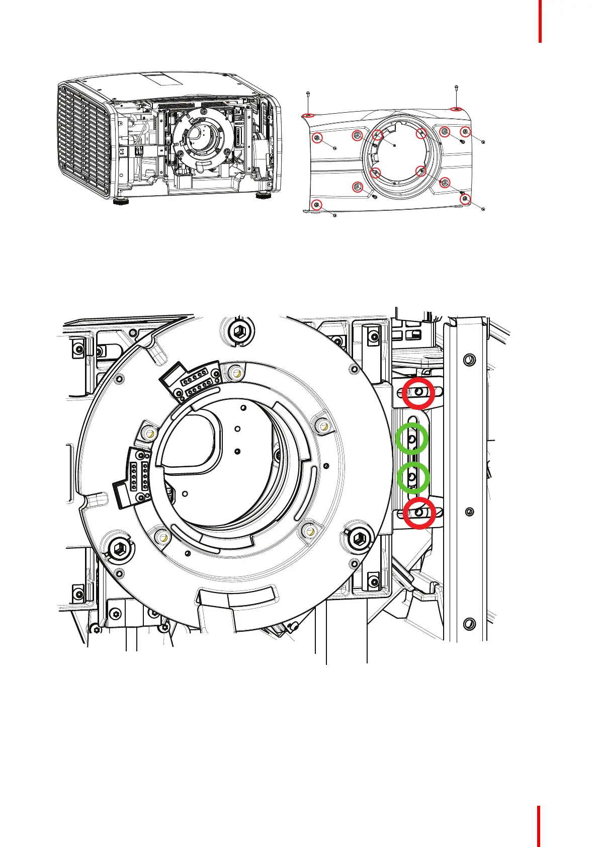
Image 9-2
6. Insert M4 pan head screws (e.g. DIN7985 Torx. Not supplied) with a maximum length of 15mm in the threaded
holes, indicated by the red and green circles in the illustration below. Tighten the screws with a sufficient
torque according to good workmanship. (No torque value specified). The green circles indicate the lock for the
vertical shift, and the red circles indicate the lock for the horizontal shift. All four locking positions must be used
to achieve a sufficient locking.
Image 9-3
Lenses and adjustment