Operating instructions CS 300 Installation
6.110.98.5.01.40 en 4 - 17
4
For installing and deinstalling the scanner adhere to the installation in-
structions of the scanner manufacturer.
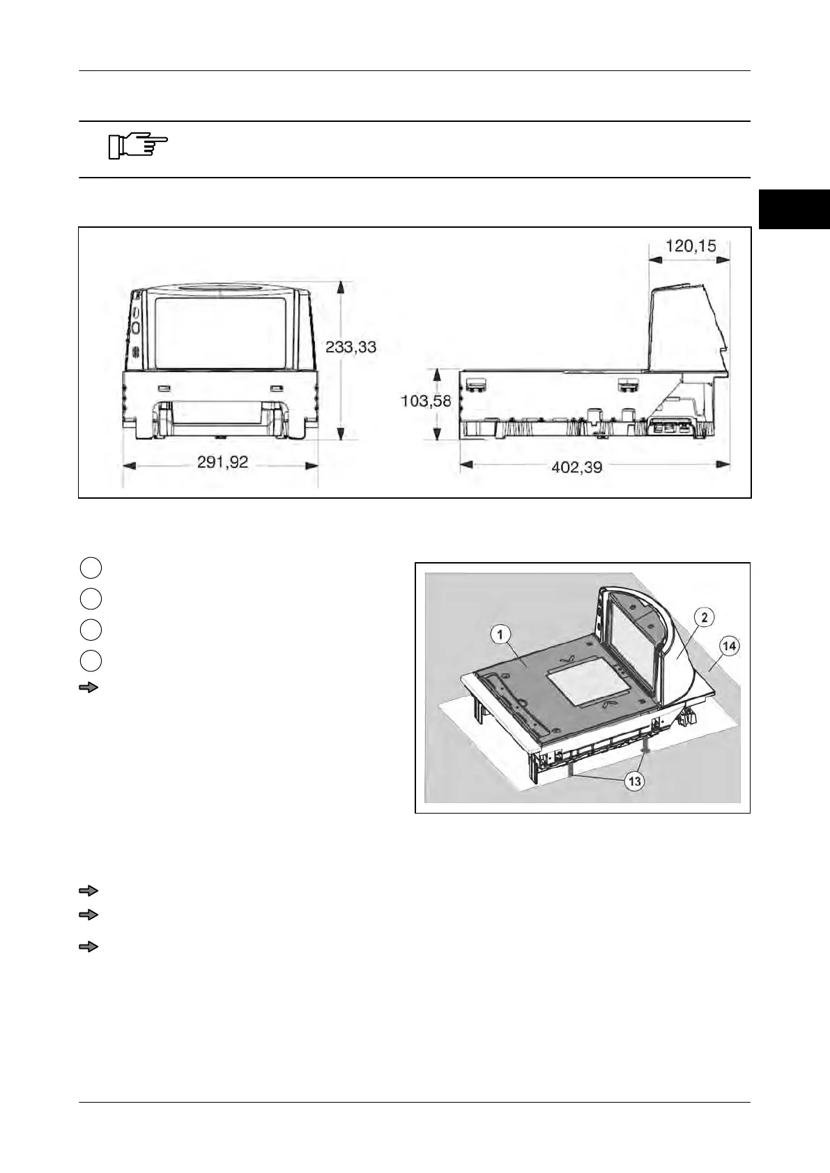
Dimensions of scanner with weighing system
Fig. 28: Dimensions CS 300 MA 84
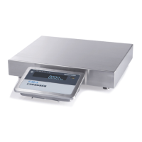
Installation in POS counter
Fig. 29: Installation of CS 300 MA 84 in POS
counter
Load platter
Scanner
Foot screws (4 pcs.)
POS counter
Insert the scanner with weighing sys-
tem into the counter cutout, see also in-
structions from scanner manufacturer.
Please make sure that the load platter is
on the same height level as the POS
counter.
Adjust load platter
Place the load platter on the load platter supports of the weighing system.
Adjust the load platter to the height of the POS counter by means of leveling.
Check the distance between the load platter and the lateral limitations of the scanner
housing.
There must be an even gap of approx. 2 mm between the load platter and lateral limi-
tations of the scanner housing.