Installation Operating instructions CS 300
4 - 12 6.110.98.5.01.40 en
4
Connecting the scale CS 300 ER-K
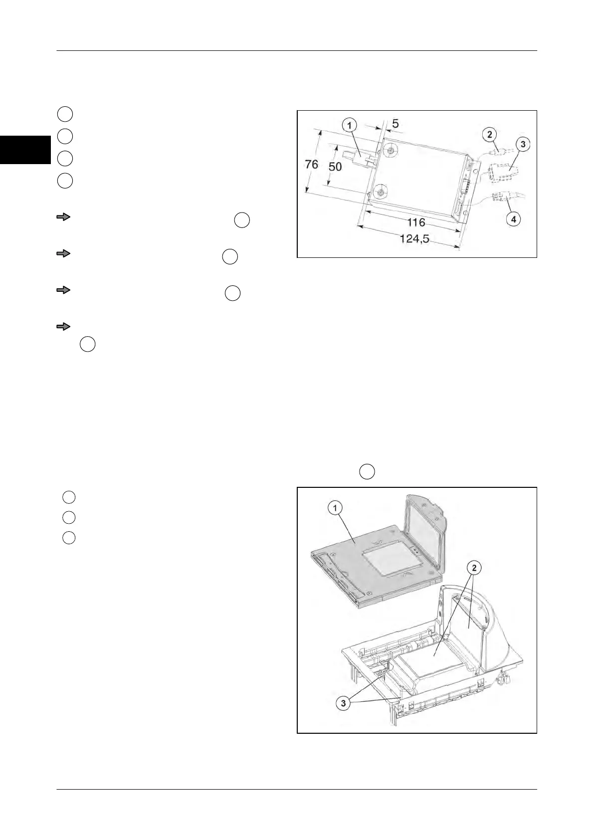
Fig. 20: Electronics box
Scale cable
Connector for power supply
POS connector
Display connector
Lay and connect cables
Route display cable properly
and
connect it to electronics box.
Route POS cable properly
and con-
nect it to electronics box.
Route scale cable properly
and con-
nect it to electronics box.
Insert connector for power supply cable
into electronics box and and lay it
properly toward the socket.
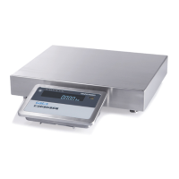
4.5.4 CS 300 MA 84
Scanner (8300/8400)
The scanner is designed for mounting of weighing system. See instructions provided by
scanner manufacturer.
The cover plate of the scanner serves as the load platter
.
Load platter
Scanner
Threaded holes for weighing system
Fig. 21: Scanner