Installation Operating instructions CS 300
4 - 24 6.110.98.5.01.40 en
4
Distance to POS counter
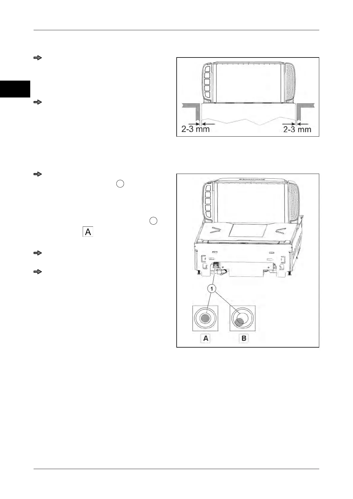
Fig. 41: Size POS counter cut-out MA 94
When installing the scanner in the POS
counter, make sure that there is a clear-
ance of 2-3 mm between load platter
and lateral limitations of the POS coun-
ter on all sides.
Adjust deviations by suitable measures,
e.g. check POS counter, align weighing
system etc.
Leveling
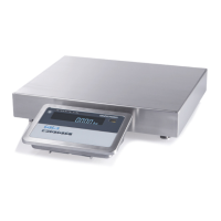
Fig. 42: Spirit level MA 94
Level the scanner (weighing system) by
means of a spirit level
by aligning the
POS counter or adjusting the foot
screws or by any other possible meas-
ure.
If the air bubble in the spirit level
is in
the center , as shown in the picture,
the scale is in horizontal position.
Reattach the load platter and check if
the scale is installed correctly.
Check the scale for freedom of move-
ment.
see page 4 - 4