Operating Instructions ACU
9.2.10.1 Acceleration and deceleration
The settings define how fast the output frequency changes after a reference value change or a start,
stop or brake command.
The deceleration of the drive is monitored in the default parameter Operation Mode
Voltage Controller 670. The deceleration ramp can be extended in the case of an
increase in the DC link voltage during regenerative operation and/or during the braking
process.
9.2.10.2 Set points at multifunction input
Multifunction input MFI1 can be parameterized for a reference value signal in Operation Mode 452.
Operation Mode 3 should only be selected by expert users for drive control via Fixed Frequency 1
480 and Fixed Frequency 2 481.
voltage signal (MFI1A), 0 V ... 10 V
current signal (MFI1A), 0 ...20 mA.
digital signal (MFI1D), 0 V ... 24 V
Use multifunction input MFI1 as digital input for slow signals. For rapidly and regularly
changing signals, use a digital input S2IND…S6IND or a digital input of an extension
module EM.
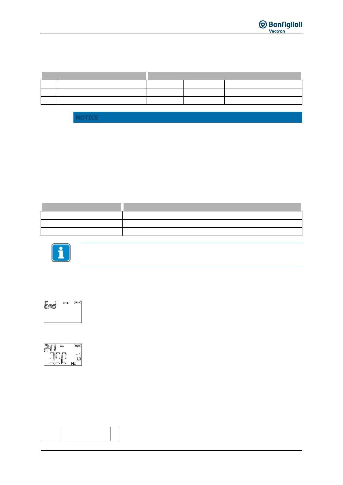
9.2.11 Quitting commissioning
Confirm the "End" display by pressing the ENT key.
The guided commissioning of the frequency inverter is terminated via a reset and
the initialization of the frequency inverter. Relay output X10 reports a fault due to
default setting Op. Mode Digital Output 3 532 = „103 - Inv. Error Signal“ (Inv:
inverted).
After successful initialization of the frequency inverter, the factory-set parameter
Actual Frequency 241 is displayed.
The drive is accelerated to the set Min. Frequency 418 (default: 3.50 Hz in
Configurations 110, 111, 410, 411, 430 or 0.00 Hz in Configurations 210, 211, 230,
510) by:
signals at digital inputs S1IND/STOA (STOA) and S7IND/STOB (STOB) and
Start clockwise by rising signal edge at S2IND orStart anticlockwise by rising
signal edge at S3IND
Signals that frequency inverter has been initialized and is ready for
operation.