Operating Instructions ACU
If the parameter Trigger Threshold 506 is set to a value below the DC link voltage generated by the
mains, error message F0705 (chapter 21.1.1"21.1.1") is displayed if the start command is issued to
the frequency inverter.
If the DC-Link Voltage exceeds a certain threshold, error message F0700 will be triggered (see
Chapter 21.1.1 "21.1.1"). The threshold depends on the device series:
ACU 201 device series: 400 V
ACU 401 device series: 800 V
ACU 501 device series: 900 V
ACU 601 device series: 1200 V
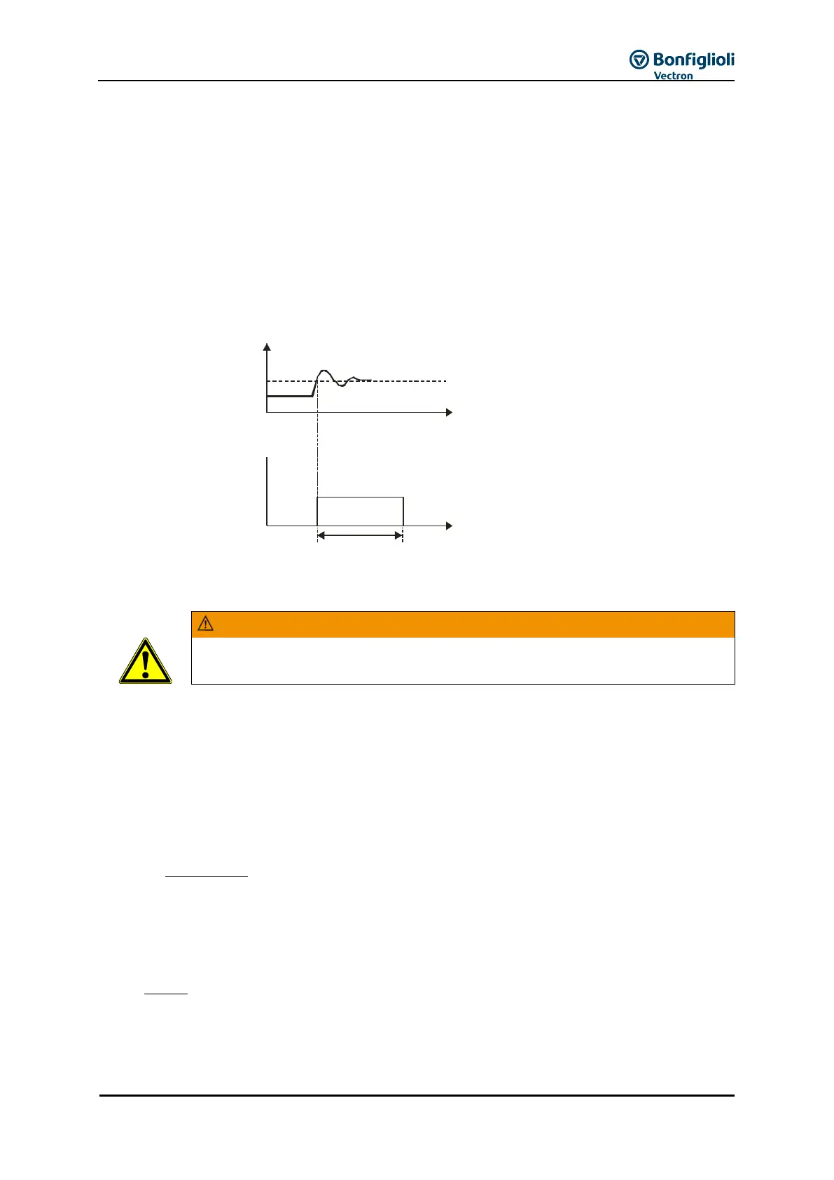
The sampling time of the function is 125 µs. The brake chopper remains on for at least 125 µs after
the set trigger threshold was exceeded even if the value drops below the trigger threshold within
this period again.
Brake chopper
ON
OFF
125 sµ
t
U
d
Trigger Threshold 506
t
19.4.1 Dimensioning of brake resistor
The brake resistor is to be connected according to the specifications and instructions
in chapter 7.4.4 "7.4.4".
The following values must be known for dimensioning:
Peak braking power P
b Peak
in W
Calculation of peak braking power P
b Peak
b
2
2
2
1
Spitze b
t182
nnJ
P
Moment of inertia of drive system kgm
2
Speed of drive system before the braking operation in rpm
Speed of drive system after the braking operation in rpm
Calculation of resistance R
b
The switch-on threshold U
d BC
is the DC link voltage at which the brake resistor is switched on. The
switch-on threshold can be set, as described above, via parameter Trigger Threshold 506.