Operating Instructions ACU
22 Operational and error diagnosis
Operation of the frequency inverter and the connected load are monitored continuously. Various
functions document the operational behavior and facilitate the operational and error diagnosis.
22.1 Status display
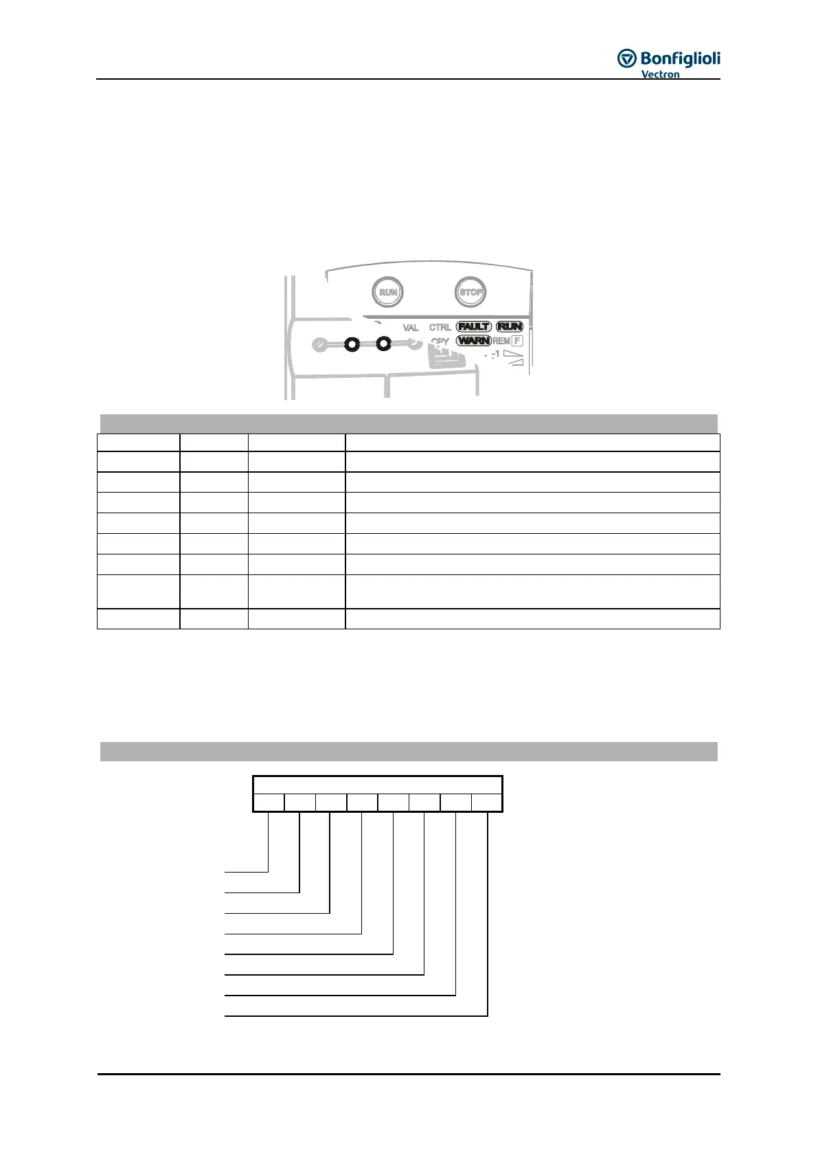
The green and red light-emitting diodes give information about the operating point of the frequency
inverter. If the control unit is connected, the status messages are additionally displayed by the
display elements RUN, WARN and FAULT.
initialization and self-test.
Operating message, current Warning 269.
Ready for operation, current Warning 269.
Last Error 310 of frequency inverter.
Last Error 310, acknowledge fault.
22.2 Status of digital signals
The status display of the digital input and output signals enables checking of the various control
signals and their assignment to the corresponding software functions, in particular during
commissioning.
Coding of the status of the digital signals