Operating Instructions ACU
The power output stage is deactivated by disabling frequency inverter control at S1IND/STOA and
S7IND/STOB. The motor will coast to a stop or a brake will be activated, if installed.
9.4 Speed sensor
In some configurations, an incremental speed sensor must be connected. Depending in the type of
speed sensor , it is connected to the basic device or an extension module. In some cases, speed
sensors are connected to both the basic device and the extension module.
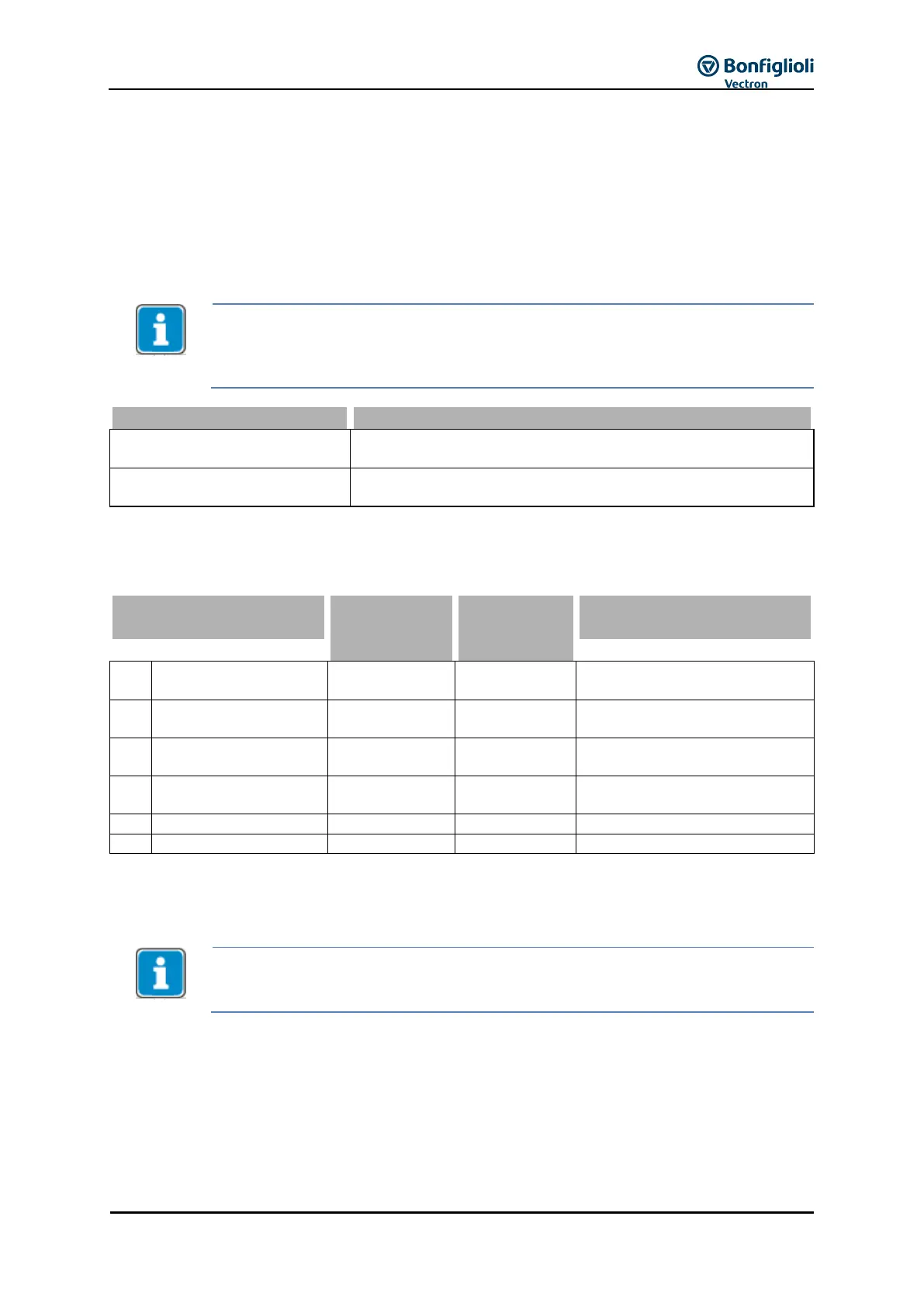
The actual speed source is selected via parameter Actual Speed Source 766. In the
default setting, Speed Sensor 1 is used as the source of actual speed. If Speed Sensor
2 of an extension module is to deliver the actual value signal for the speed controller,
Speed Sensor 2 must be selected as the source.
The actual speed source is speed sensor 1 of the basic device
(factory setting).
The actual speed source is speed sensor 2 of an extension
module.
1)
1)
Only available if extension module is installed
Depending on the application and speed sensors used, the parameter settings must be adjusted
according to the following table:
Operation Mode Speed
Sensor 1
Division Marks, Speed
Sensor 1
Operation Mode Speed
Sensor 2
Division Marks, Speed
Sensor 2
X Value is not evaluated, any value is possible.
The parameters listed above can be selected depending on the configuration selected and/or if an
extension module is available.
Two speed sensors are required in some applications. The Actual Speed Source 766
must be set to the motor sensor for motor control. The other speed sensor is used as
external sensor. Refer to application manuals “Electronic Gear” and “Positioning”.
9.4.1 Speed Sensor 1
The track signals of the speed sensor are to be connected to digital inputs S5IND (track A), S4IND
(track B) and S6IND (track Z).
The speed sensor type and evaluation required are set via Operation Mode 490 of Speed Sensor 1.
For detailed setting options, refer to Chapter 11.4 "11.4".