Operating Instructions ACU
Digital input STOB (2nd shut-down
path of STO safety function)
Analog signal of actual frequency
Actual percentage value 0 ...+10 V
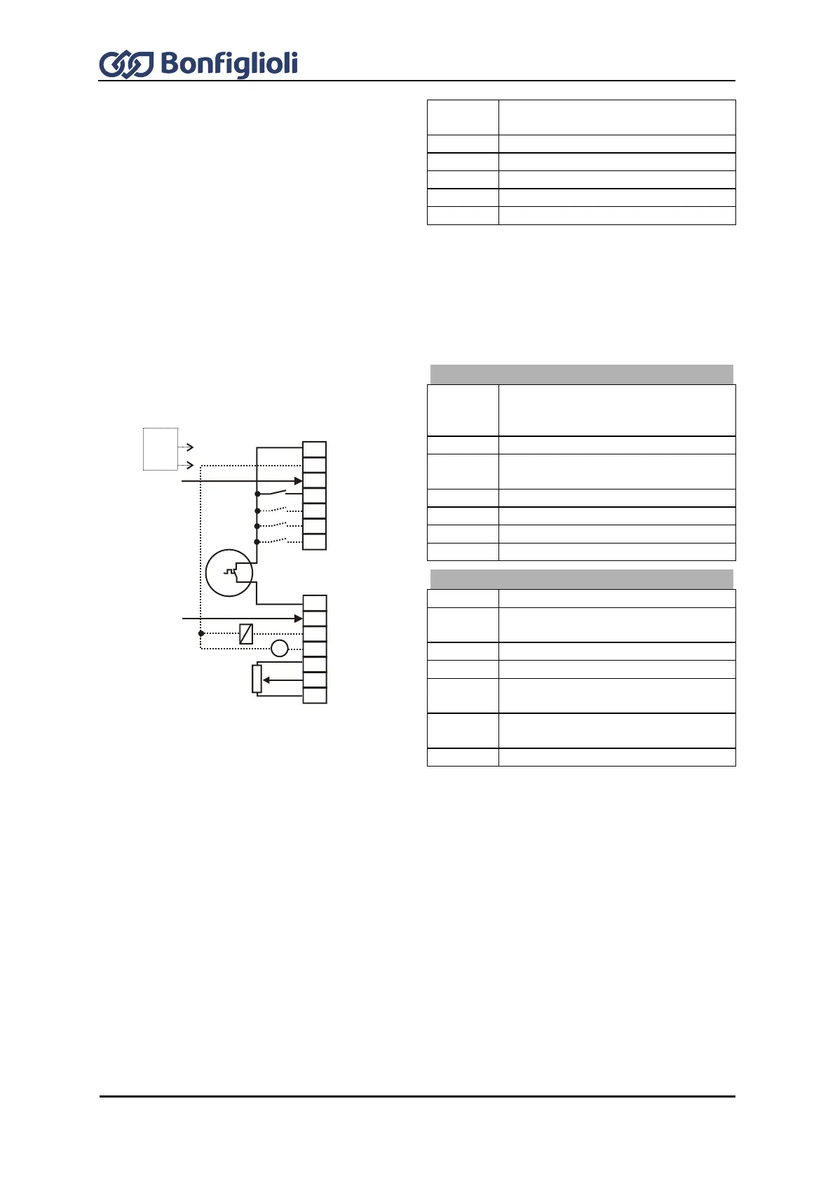
7.8.14 Configuration 630 – Sensorless Field-Oriented Control of a
Synchronous Machine Speed and Torque Controlled
Configuration 630 extends the functionality of the sensorless field-oriented control of Configuration
610 by a Torque Controller. The reference torque is represented as a percentage and it is transmitted
into the corresponding operational performance of the application. Change-over between variable-
speed control and torque-dependent control is done jerk-free during operation.
Voltage output +20 V or input for
external power supply DC 24 V
±10%
GND 20 V/ GND 24 V (ext.)
Digital input STOA (1st shut-down
path of STO safety function)
Start of clockwise operation
n-/M change-over control function
Digital input STOB (2nd shut-down
path of STO safety function)
Analog signal of actual frequency
Supply voltage +10 V for reference
value potentiometer
Reference speed 0...+10 V or
reference torque as percentage
7.9 Notes on installation as per UL508c
Thermal motor protection as per UL508c can be realized in devices marked with “TM included” under
the nameplate. For ACU devices without the “TM included” label, the following applies as per UL508c:
Motor overtemperature identification not featured by the device.
For connection and parameterization of the thermal motor evaluation, refer to Chapter 14.6 "Motor
temperature", 16.4.5 "Thermocontact" and 19.5 "Motor circuit breaker".
For installation as per UL508c, the mains feeder may only be protected using approved fuses. For
approved fuses, refer to Chapter 5 "Technical data".
For installation as per UL508c, the maximum temperatures specified in Chapter 5 "Technical data"
must not be exceeded.
For installation as per UL508c, only copper cables with a rated current of 60/75°C may be used.
For installation as per UL508c, the devices may only be used in "Pollution Degree 2" environments.
According to UL508c, warnings and markings/labels must not be removed.
S7IND
S1OUT
MFO1A
+10 V/ 4 mA
MFI1A
GND 10 V
1
2
3
4
5
6
7
X210A
+20 V/180 mA
GND 20 V
S1IND
S2IND
S3IND
S4IND
S5IND
S6IND
X210B
1
2
3
4
5
6
7
M
V
+
-
+
-
STOA
STOB
24 V
ext.