Operating Instructions ACU
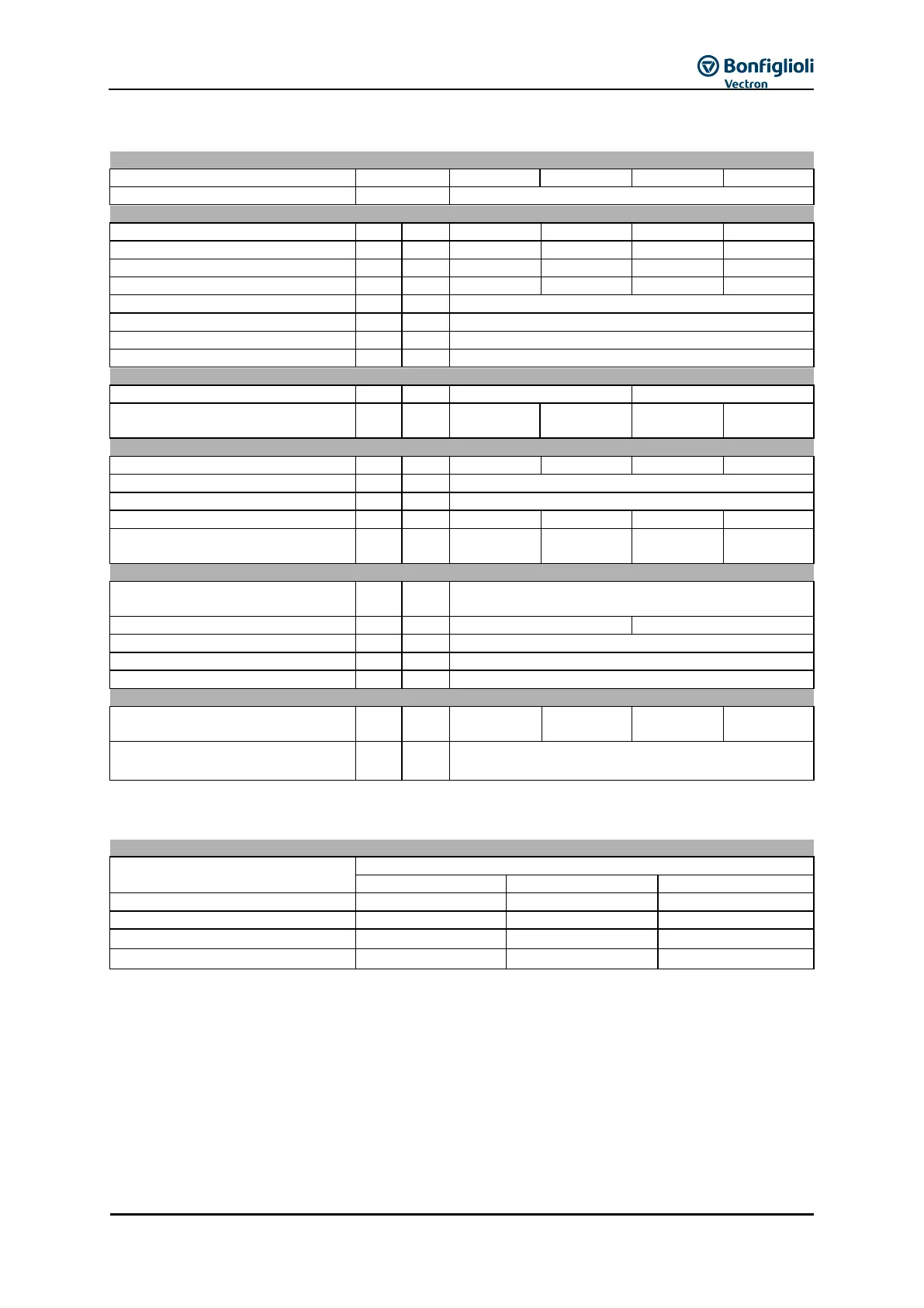
5.11 ACU 401 Size 7 (75.0 to 132.0 kW, 400 V)
Recommended motor shaft power
Long-term overload current (60 s)
Short-time overload current (1 s)
Maximum input voltage, three-phase
Short circuit / earth fault proof
0 ... 599, depending on switching frequency
Output, braking resistor
(external) 5)
Recommended braking resistor
(U
dBC
= 770 V)
Fuses as per UL
6)
Cooper Bussmann
Ingress protection rating
Energy dissipation (2 kHz switching
frequency)
Coolant temperature for air cooling
7)
0 ... 40 (3K3 DIN IEC 721-3-3)
If required by the customer, the switching frequency may be increased if the output current is reduced at the
same time. Comply with the applicable standards and regulations for this operating point.
Frequency inverter nominal power
1)
Three-phase connection requires a commutating choke.
2)
Mains current with relative mains impedance ≥ 1% (see Chapter 7 "Electrical installation")
3)
Reduction of switching frequency in thermal limit range
4)
Maximum current in continuous operation
5)
As an option, the frequency inverter of this size is available without internal brake transistor.
6)
For UL-compliant fusing, the specified Cooper Bussmann fuses must be used. Other fuses must not be used for
UL-conforming fusing.
7)
Coolant temperature for liquid cooling: see “Operating Instructions Liquid Cooling Supplemental“