Operating Instructions ACU
11.4.2 Division Marks, Speed Sensor 1
The number of increments of the connected speed sensor can be adjusted via parameter Division
Marks Speed Sensor 1 491. Select the division marks of the speed sensor according to the speed
range of the application.
The maximum number of division marks S
max
is defined by the frequency limit of f
max
=150 kHz of the
digital inputs S5IND (track A) and S4IND (track B).
6000
1500
60s
Hz 150000
max
S
= 150000 Hz
= max. speed of the motor in RPM
To guarantee true running of the drive, an encoder signal must be evaluated at least every 2 ms
(signal frequency f = 500 Hz). The minimum number of division marks S
min
of the incremental
encoder for a required minimum speed n
min
can be calculated from this requirement.
1500
102
s 60
Hz 500
min
S
= min. speed of the motor in RPM = evaluation (1,
2, 4)
Division Marks, Speed Sensor 1
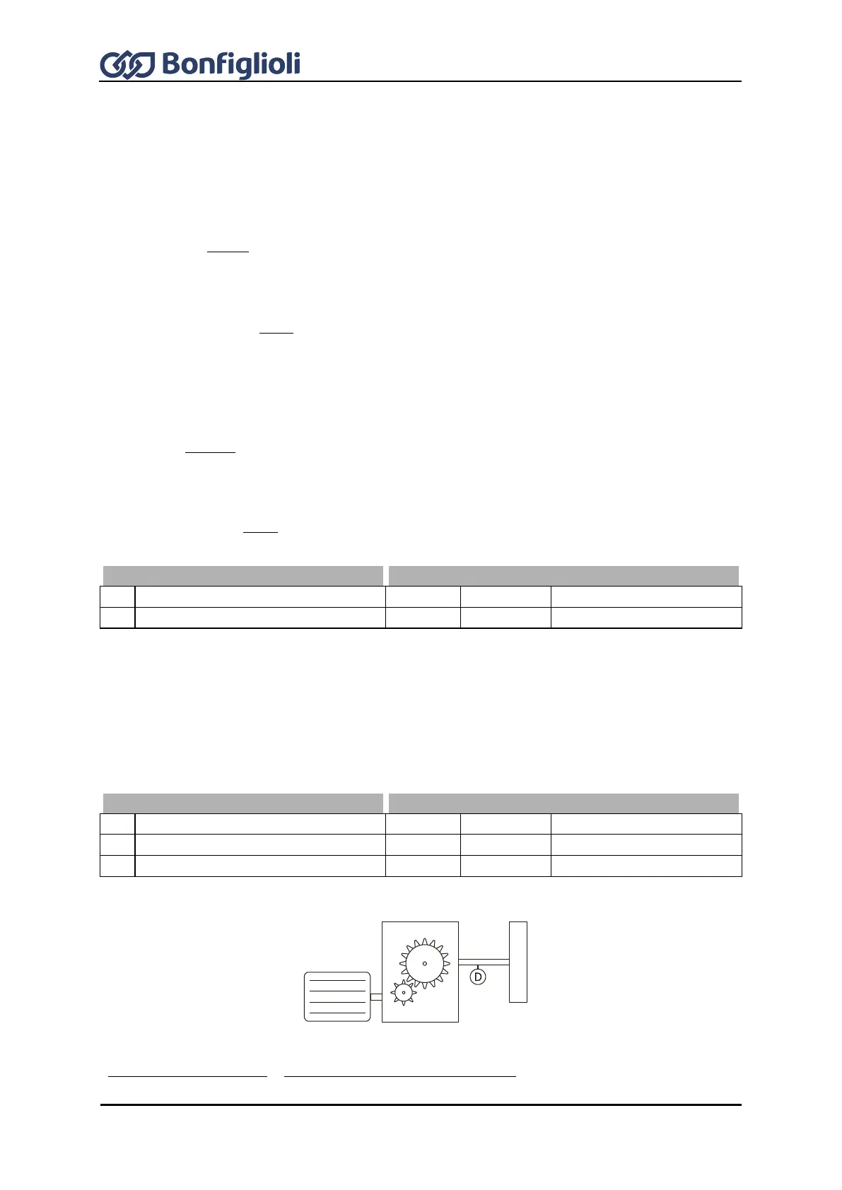
11.4.3 Gear factor speed sensor 1
Setting of parameters EC1 Gear Factor Numerator 511 and EC1 Gear Factor Denominator 512 is
required if a gear is installed between the speed sensor and the motor shaft. The parameters define
the mechanical transmission ratio between the speed sensor and the motor side. The parameters
must be set such that the gear factor numerator corresponds to the motor rotations and the gear
factor denominator corresponds to the sensor rotations.
EC1 Gear Factor Numerator
EC1 Gear Factor Denominator
Example: The motor shaft turns twice while the load shaft rotates once (16/8).
512
511
axis load of sRevolution
axismotor of sRevolution
rDenominato Factor Gear 1 EC
Numerator Factor Gear 1 EC
Load
Encoder
Gear
Motor
8 teeth
16 teeth