Operating Instructions ACU
12 System data
The various control functions and methods according to the selected Configuration 30 are
supplemented by control and special functions. For monitoring the application, process parameters
are calculated from electrical control parameters.
12.1 Actual value system
Parameter Factor Actual Value System 389 can be used if the drive is monitored via actual value
Actual Value System 242.
The Actual Frequency 241 to be monitored is multiplied by the Factor Actual Value System 389
and can be read out via Parameter Actual Value System 242 , i. e. Actual Frequency 241 x Factor
Actual Value System 389 = Actual Value System 242.
Factor Actual Value System
12.2 Volume Flow and Pressure
Parameterization of factors Nominal Volumetric Flow 397 and Nominal Pressure 398 is necessary
if the matching actual values Volumetric Flow 285 and Pressure 286 are used for drive monitoring.
The conversion is done using the electrical control parameters.
Volumetric Flow 285 and Pressure 286 are referred to Active Current 214 in the case of sensor-
less control methods. In the case of the field-oriented control methods, they are referred to the
torque-forming current component Isq 216.
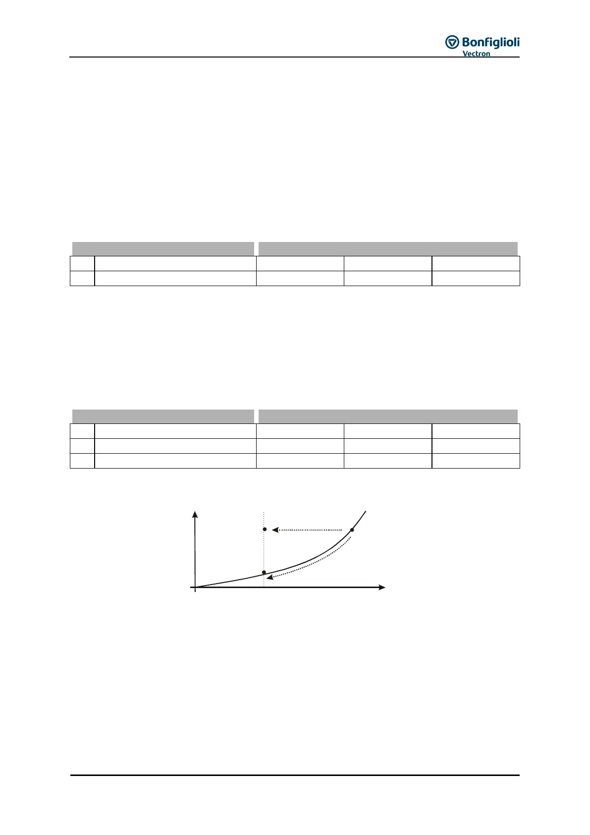
Line mains or channel characteristic:
H
kPa
Q
m /h
3
bad point method
P - method
const.
A
B2
B1
Point A in the figure describes the rating point of a pump. The transition to partial load operation
mode B1 can be effected at a constant pressure H (change of conveying flow Q, pressure H remains
constant). The transition to partial load operation mode B2 can be effected according to the bad
point method (change of pressure H and conveying flow Q). Both methods can be realized with the
integrated technology controller in configurations 111,211, 411 and 611. The actual values displayed
are calculated according to the bad point method independently of the selected Operation Mode
440 of the technology controller.