Operating Instructions ACU
Data Set Change-Over 1 is linked to the Timer 1:
Data Set Change-Over 1 70 = 158 – Timer 1
Timer 1 is linked to digital input S4IND (terminal X210A.6):
Timer 1 83 = 73 – S4IND
By default, Data Set Change-Over 1 is not affected by Timer 1:
Signal delay Time 1 Timer 1 791 = 0.00 s/m/h
Signal duration Time 2 Timer 1 792 = 0.00 s/m/h
16.4.8 Fixed Value Change-Over
Depending on the selected configuration, the setpoints are defined via the assignment of the
Reference Frequency Source 475 or Reference Percentage Source 476. Accordingly, there can be a
change between the fixed values by connection of the logic signals with parameters Fixed
Frequency Change-Over 1 66, Fixed Frequency Change-Over 2 67 or parameters Fixed Percent
Change-Over 1 75, Fixed Percent Change-Over 2 2 76.
By combining the logic states of the fixed frequency change-over modes 1 and 2, fixed frequencies 1
through 4 can be selected:
Fixed Frequency
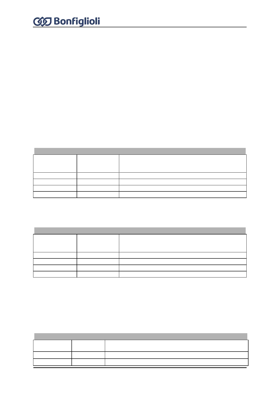
Change-Over 1 66
Fixed Frequency
Change-Over 2
67
Function/active fixed value
0 = Contact open 1 = Contact closed
By combining the logic states of the fixed percentage change-over modes 1 and 2, fixed percentages
1 through 4 can be selected:
Fixed Percent
Change-Over 1 75
Fixed Percent
Change-Over 2
76
Function/active fixed value
0 = Contact open 1 = Contact closed
16.4.9 Motor potentiometer
Parameters Reference Frequency Source 475 and Reference Percentage Source 476 contain
operation modes with motor potentiometer. Operation Mode 474 defines the behavior of the motor
potentiometer function and parameters Frequency Motorpoti Up 62, Frequency Motorpot. Down 63
or Percent Motorpoti Up 72, Percent Motorpoti Down Ab 73 the link to the available logic signals.
Motor Potentiometer Control
Output signal does not change
Output value rises at set ramp