Operating Instructions ACU
Connect the shield close to the frequency inverter and limit the length to the necessary minimum.
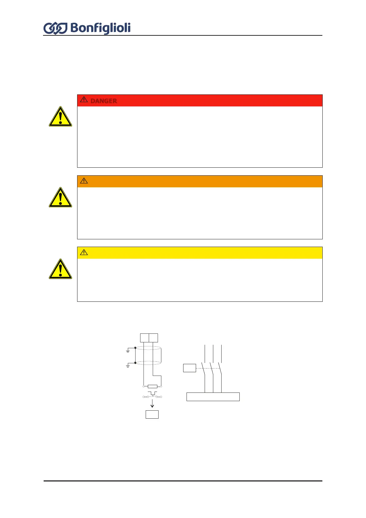
7.4.4 Connection of a braking resistor
Install a braking resistor if feedback of regenerative energy is expected. Overvoltage shutdowns can
be avoided by this.
Disconnect the frequency inverter from mains voltage and protect it against being
energized unintentionally.
Verify safe isolation from power supply.
Work on the device may only be started once the DC link capacitors have discharged.
The time to wait is at least 3 minutes in the case of sizes 1 through 7.
When the frequency inverter is disconnected from power supply, the mains, DC-link
voltage and motor terminals may still be live for some time.
The surface of the braking resistor may reach a high temperature during operation and
may remain hot for some time after operation. Do not touch the braking resistor while
the frequency inverter is in operation or ready for operation. Non-compliance may result
in burns. Install a safeguard to prevent touching or provide a warning sign.
Do not install the braking resistor near inflammable or heat-sensitive materials.
Do not cover the braking resistor.
Bonfiglioli Vectron MDS GmbH recommends using a temperature switch. Depending on
the resistor selected, the temperature switch is integrated as a standard or available as
an option. The temperature switch disconnects the frequency inverter from mains
supply if the braking resistor is overloaded.
Using braking resistors without temperature switches may result in critical situations.
Braking resistors are connected via terminal X2.
Limit the length of the braking resistor cables to the necessary minimum.
L1
L2
L3
K1
K1
R
b
T1
Rb1 Rb2
T2
Rb2Rb1
X2
X1

 Loading...


