Operating Instructions ACU
16.1.1.5 Error and warning behavior
For monitoring the analog input signal, an operation mode can be selected via parameter
Error/Warning Behavior 453 .
Error/Warning Behavior 453
The input signal is not monitored.
If the input signal is lower than 1 V or 2 mA, a warning message
is issued.
If the input signal is lower than 1 V or 2 mA, a warning message
is issued; the drive is decelerated according to stopping behavior
2.
Error switch-off
< 1V/2 mA
If the input signal is lower than 1 V or 2 mA, a warning and
error signal is issued and the drive coasts to a standstill
(stopping behavior 0).
Monitoring of the analog input signal is active regardless of the release of the frequency inverter
according to the operation mode selected.
Operation Mode 2 2 defines the shut-down and stopping of the drive, regardless of the setting of
parameter Operation Mode 630 for the stopping behavior. The drive is stopped according to
stopping behavior 2. If the set holding time has expired, an error message is issued. The drive can
be started again by switching the start signal on and off.
Operation Mode 3 defines the free coasting of the drive, regardless of the setting of parameter
Operation Mode 630 for the stopping behavior.
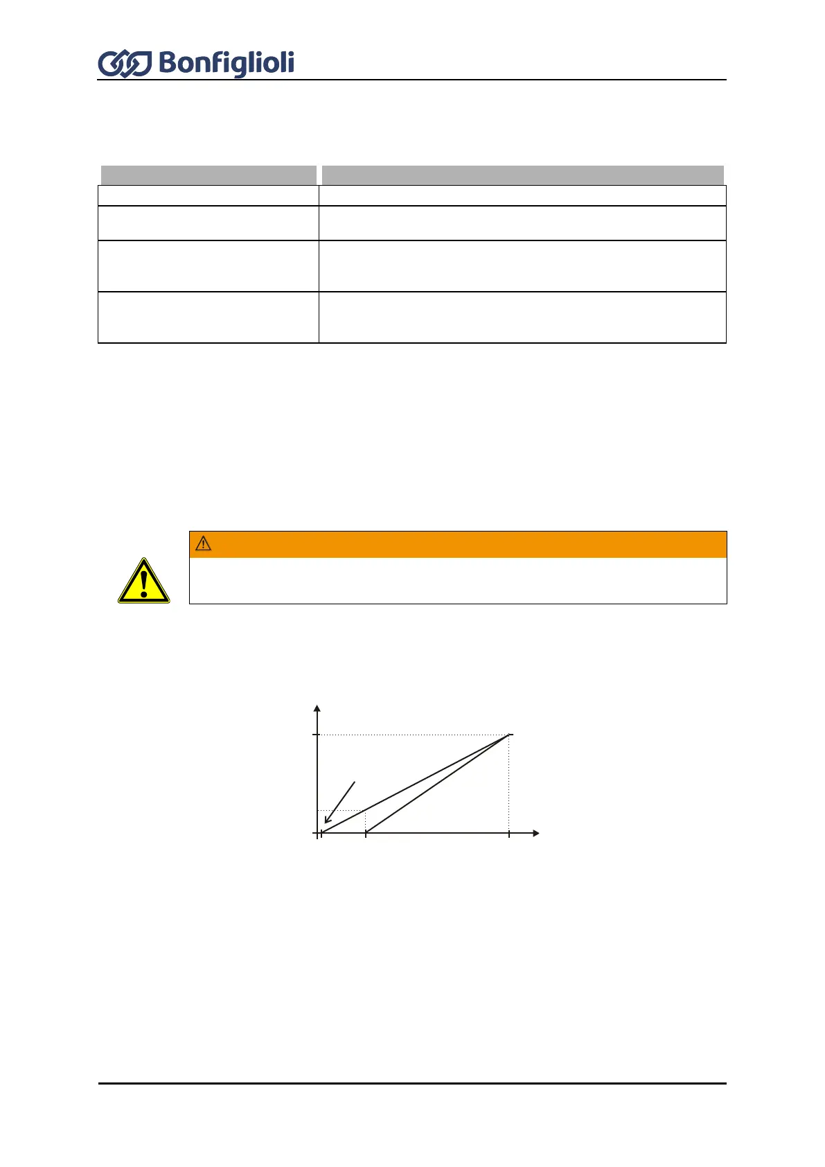
The monitoring of the analog input signal via the parameter Error/Warning Behavior
453 demands the examination of parameter Point X1 454.
Example: Error/Warning Behavior 453 = “2 - Shutdown < 1V/2mA” or “3 - Error-Switch-Off <
1V/2mA”. In the default settings of parameter Point X1 454 shutting down or fault switch-off are
effected at an output frequency ≠ 0Hz. If shutting down or fault switch-off are to be effected at an
output frequency of 0 Hz, the Point X1 must be adjusted (e.g. X1=10% /1 V).
50 Hz
9,8 V0,2 V
Y
X
0 Hz
(X1=2% / Y1=0%)
1 V