Operating Instructions ACU
Max. permissible
short-circuit
current to be
expected with
mains supply
Up to 132 kW device power (size 7): 5 kA
The frequency inverters are designed for Pollution Degree 2.
The frequency inverters are designed for Overvoltage Category III.
Control methods adjusted to motors and application (configuration).
Adjustable speed/torque control.
Various protection functions for motor and frequency inverter.
Positioning absolute or relative to a reference point.
Catching function.
Special brake control and load detection for lifting gear.
S-ramps for jerk limitation during acceleration and deceleration.
Technology (PI) controller.
Parameterizable Master-Slave operation via system bus.
Error memory.
Simplified and extended control via PC (commissioning,
parameterization, data set backup, diagnosis with Scope).
Freely programmable digital inputs and outputs.
Various logic modules for linking and processing of signals.
Four separate data sets incl. motor parameters.
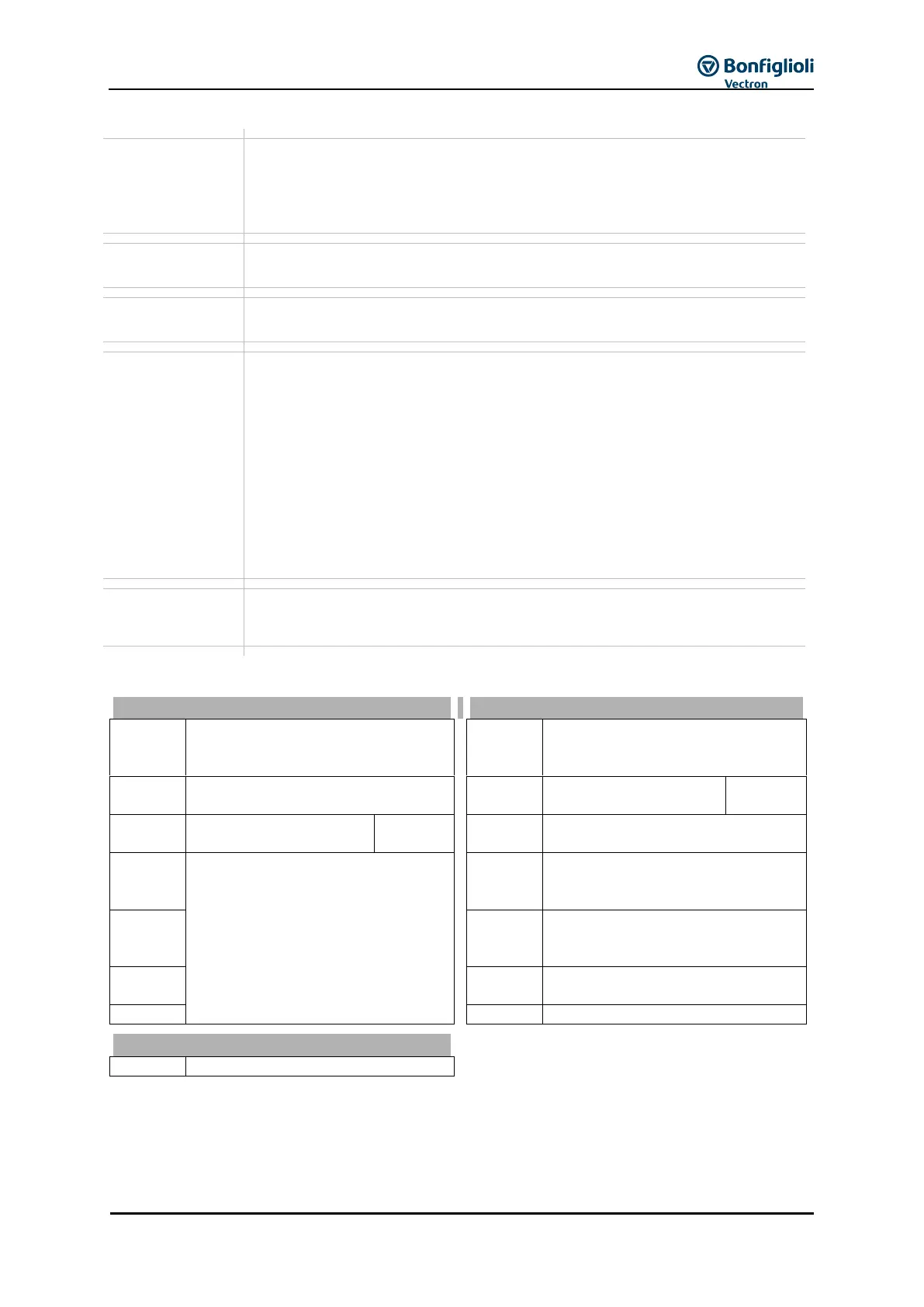
5.2 Technical Data – Control Electronic Equipment
DC 20 V output (I
max
=180 mA)
or DC 24 V ±10% input for
external power supply
GND 20 V/ GND 24 V (ext.)
Digital input STOB
(second shut-down path)
Digital input STOA
(first shut-down path)
Multifunction output
1)
(voltage
signal, proportional act. frequency,
factory settings)
Supply voltage DC 10 V for
reference value potentiometer,
(I
max
=4 mA)
Multifunction input
1)
(reference
speed 0 … +10 V, factory settings)
Inverter error message
1)
1)
Control terminals are freely configurable.
Control “Safe Torque Off”: Contacts on X210A.3 and X210B.2 open.
Release of frequency inverter: Contacts on X210A.3 and X210B.2 closed.