Operating Instructions ACU
16.3.8 Warning mask
The warning mask signals, via a digital signal, if a pre-configured warning is present. The warning
mask is configured via Create Warning Mask 536. Warnings and controller status messages can be
combined. This enables internal or external control using a common output signal. The display of
269 Warning and 275 Controller Status is not influenced via the warning mask.
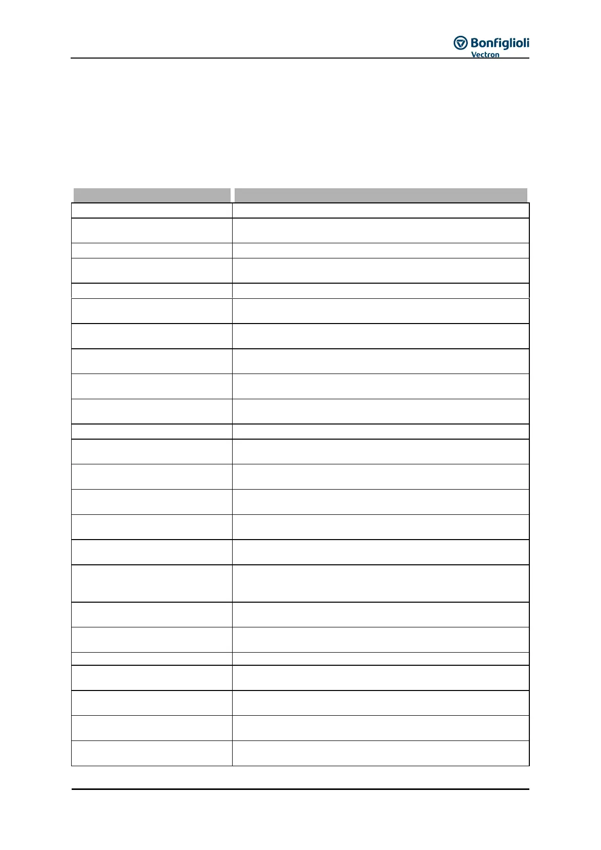
Select one of the settings 1 … 43 to activate messages.
Select one of the Operation Modes 101 … 143, if certain warnings are not to be reported.
Configured warning mask is not modified.
The warnings and controller status messages stated are linked in
the warning mask.
The warnings reports stated are linked in the warning mask.
Activate all controller states
The controller status reports stated are linked in the warning
mask.
The frequency inverter is overloaded
Overload reserve for 1 s minus the Warning Limit Short Term
Ixt 405 was reached.
Overload reserve for 60 s minus the Warning Limit Long Term
Ixt 406 was reached.
Warning heat sink
temperature
Max. heat sink temperature TK of 80 °C minus the Warning Limit
Heat Sink Temp. 407 was reached.
Warning inside temperature
Max. Inside Temperature T
i
of 65 °C minus Warning Limit
Inside Temp. 408 reached.
The controller stated in Controller Status 355 limits the
reference value.
Frequency inverter is being initialized
Motor temperature warning
Waring behavior as per configured Motor Temp. Operation Mode
570 at max. motor temperature T
PTC .
Phase Supervision 576 reports mains failure.
Operation Mode 571 for motor circuit breaker was triggered.
The Maximum Frequency 419 was exceeded. The frequency
limitation is active
Warning
Analog Input MFI1A
The input signal is lower than 1V/2mA according to the
operation mode Error/Warning Behavior 453.
Warning
Analog Input EM-S1INA
The input signal at the analog input of an extension module is
lower than 1V/2mA according to the operation mode
Error -/Warning Behavior 453.
A slave on the system bus reports a fault;
warning is only relevant with the EM-SYS option.
The DC link voltage has reached the type-dependent minimum
value.
A warning application is signaled.
Controller
Udc Dynamic Operation
Controller is active according to the Operation Mode 670 for the
voltage controller.
The output frequency in the case of a power failure is below the
Shutdown threshold 675.
Failure of the mains voltage and power regulation active
according to Operation Mode 670 for the voltage controller.
Controller Udc limitation
The DC link voltage has exceeded the Reference DC-Link
Limitation 680.