Operating Instructions ACU
7.3 Optional components
Due to modular hardware components, the frequency inverters can be integrated in the automation
concept easily. The standard and optional modules are recognized during the initialization, and the
controller functionality is adjusted automatically. For the information required for installation and
handling of the optional modules, refer to the corresponding documentation.
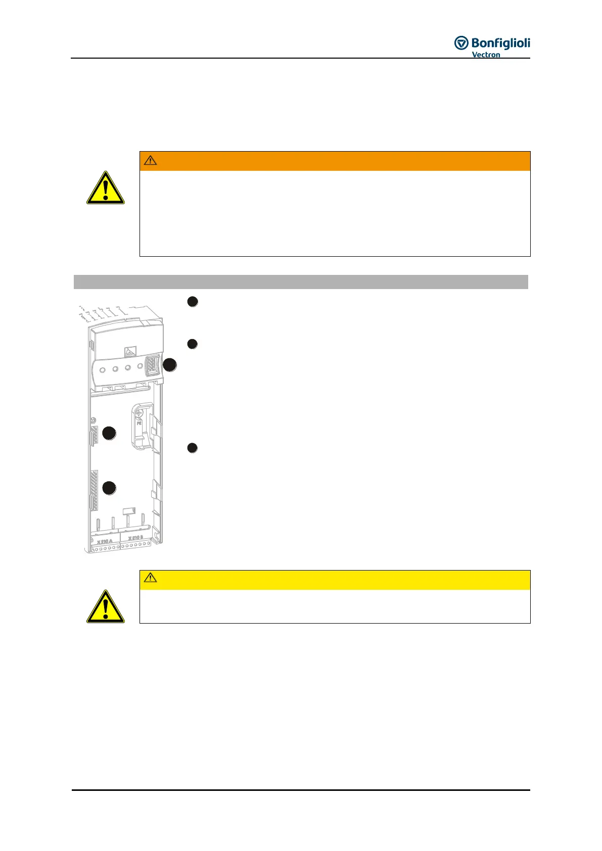
The hardware modules at slots B and C may only be assembled and disassembled
after the frequency inverter has been disconnected safely from power supply. Work
on the device may only be started once the DC link capacitors have discharged. The
discharge time is at least 3 minutes in the case of sizes 1 through 7.
The unit may only be connected with the power supply switched off.
Verify safe isolation from power supply.
Connection of the optional control unit KP500 or an interface adapter
KP232.
Slot for connection to various communication protocols:
CM-232: RS232 interface
CM-485: RS485 interface
CM-PDP: Profibus-DP interface
CM-CAN: CANopen interface
Other communication modules, see Chapter 1.1 "Instruction
Manuals".
Slot for customer-specific adaptation of the control inputs and outputs to
various applications:
EM-ENC: extended speed sensor evaluation
EM-RES: Resolver evaluation
EM-ABS: Absolute encoder evaluation
EM-IO, analog and digital inputs and outputs
EM-SYS: System Bus
(system bus in combination with CM-CAN communication module upon
request)
If two optional components with CAN-Protocol controller are installed, the system bus
interface in the EM extension module is deactivated!