Operating Instructions ACU
16.1.1.2 Scaling
The analog input signal is mapped to the freely configurable characteristic. The maximum admissible
setting range of the drive can be set via the frequency limits or percentage limits according to the
configuration selected. In the case of the parameterization of a bipolar characteristic, the set
minimum and maximum limits for both directions of rotation are effective. The percentage values of
the characteristic points are relative to the limits selected.
The factory settings depend on the setup of parameter Configuration 30:
1)
3.50 Hz in configurations 1xx, 4xx;
2)
0.00 Hz in configurations 2xx, 5xx
The control system uses the maximum value of the output frequency, which is calculated from the
Maximum Frequency 419 and the compensated slip of the drive mechanism. The frequency limits
define the speed range of the drive, and the percentage values supplement the scaling of the analog
input characteristic in accordance with the functions configured.
Minimum Reference Percentage
Maximum Reference Percentage
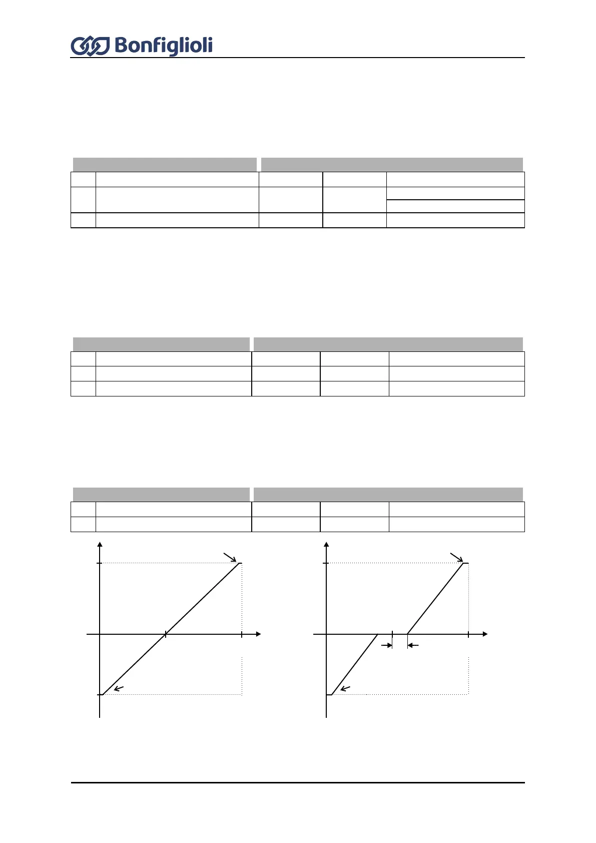
16.1.1.3 Tolerance Band and Hysteresis
The analog input characteristic with change of sign of the reference value can be adapted by the
parameter Tolerance Band 450 of the application. The adjustable tolerance band extends the zero
passage of the speed relative to the analog control signal. The parameter value (percent) is relative
to the maximum current or voltage signal.
The default Minimum Frequency 418 or Minimum Reference Percentage 518 extends the
parameterized tolerance band to the hysteresis.
pos. maximum value
neg. maximum value
0 V
(0 mA)
+10 V
(+20 mA)
(X1/Y1)
(X2/Y2)
pos. maximum value
zero point
tolerance band
neg. maximum value
0 V
(0 mA)
+10 V
(+20 mA)
(X1/Y1)
(X2/Y2)