Operating Instructions ACU
The following characteristic is set by default and can be adapted to the application via the
parameters mentioned.
Hz 0,00Hz 50,000,00%Y1
Hz 0,005Hz 50,000,00%10Y2
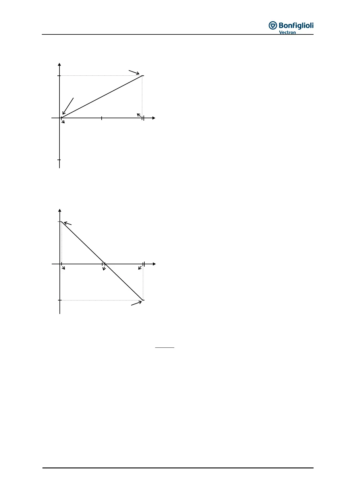
The freely configurable characteristic enables setting a tolerance at the ends as well as a reversal of
the direction of rotation.
The following example shows the inverse reference value specification with additional reversal of the
direction of rotation. This is often used in pressure control systems.
Hz 50,00Hz 50,000,00%10Y1
Hz 0,004Hz 50,000,00%8Y2
The change of direction of rotation is done in this
example at an analog input signal of 5.5 V. pos./neg.
maximum figure
The definition of the analog input characteristic can be calculated via the two-point form of the line
equation. The speed Y of the drive is controlled according to the analog control signal X.
Y1X1X
X1-X2
Y1-Y2
Y
pos. maximum value
neg. maximum value
(X1=2%/Y1=0%)
0 V
(0 mA)
50 Hz
+10 V
(+20 mA)
9.8 V
0.2 V
(X2=98%/Y2=100%)
Y
X
pos. maximum value
(X1=2%/Y1=100%)
0 V
(0 mA)
5.5 V
9.8 V0.2 V
+10 V
(+20 mA)
(X2=98%/Y2=-80%)
Y
X
-40 Hz
50 Hz
 Loading...


