Operating Instructions ACU
7.7 X13 connection in ACU 501 and ACU 601
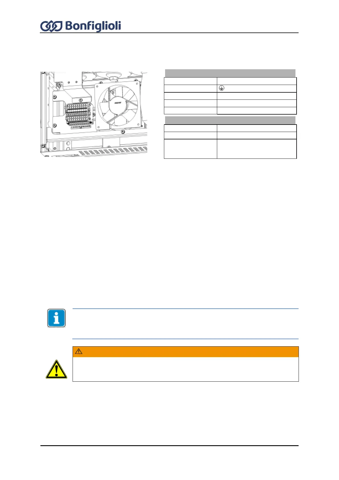
When an ACU 501 or ACU 601 device is used, connection of AC 3x400 V at X13 is required. The
illustration shows the X13 terminal on an air-cooled device as an example.
Auxiliary voltage terminal X13
7.7.1 Motor Thermo-Contact
The ACU frequency inverters can evaluate the thermal switch of motor. By default, terminal X210B.1
(S6IND) is configured as an input for this evaluation. Connect the thermal switch to the digital input
and the DC 24 V supply unit X210A.1. For parameterization, refer to Sections 14.6 “Motor
temperature” and 16.4.5 “Thermocontact”.
7.7.2 Control terminals – Wiring diagrams of configurations
The control hardware and the software of the frequency inverter are freely configurable to a great
extent. Certain functions can be assigned to the control terminals, and the internal logic of the
software modules can be freely selected.
Thanks to the modular design, the frequency inverter can be adapted to a great range of different
driving tasks.
The demands made of the control hardware and software are well known in the case of standard
driving tasks. This control terminal logic and internal function assignments of the software modules
are available in standard configurations. These assignments can be selected via Configuration 30.
The configurations are described in the following section.
The ACU devices of the ACTIVE Cube series feature the integrated STO function (“Safe
Torque Off”). If this function is not required, the “Controller release” signal must be
connected to inputs S1IND/STOA and S7IND/STOB.
Inputs S1IND/STOA and S7IND/STOB are connected in series.
The digital inputs S1IND/STOA and S2IND are driven by the same signal, safe
disconnection of energy supply to the motor as per the STO safety function (“Safe
Torque OFF”) is not guaranteed.