Operating Instructions ACU
Retrigger, Rising Edge, Sec.
Positive signal edge starts timer (trigger), next positive signal
edge within time 1 starts the signal delay again (Retrigger), time
2 defines the signal period
AND-Connect., Rising Edge,
Sec.
Positive signal edge starts timer (trigger), if no input signal is
received within time 1 the signal delay starts again (Retrigger), if
no input signal is received within time 2, the signal period is
terminated
Operation modes 1...3, negative signal edge starts timer.
Operation modes 1...3, [in minutes].
Operation modes 1...3, [in hours].
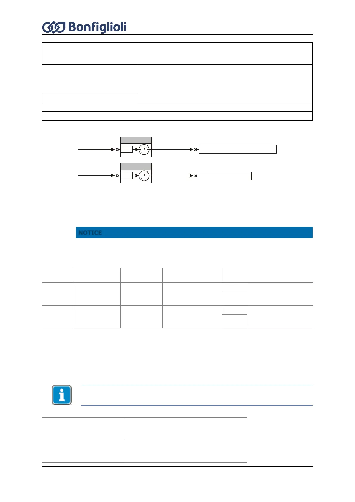
By default, the functions are linked according to the following illustration:
The sources of digital signals (z. B. 73 - S4IND) are selected with parameters Timer 1 83 and Timer
2 84. By default, Timer 1 is linked to digital input 4 and Timer 2 is off.
The timer output signal can be assigned to a frequency inverter feature or a digital output. By
default, Data Set Change-Over 1 70 is linked to Timer 1 and Timer 2 is not assigned.
Default settings: Time 2 Timer 1 792 = 0. Signals at digital input S4IND are forwarded
to Data Set Change-Over 1 without delay.
Parameter for
input signal
Output signal of function
Operation
Mode Timer 1
790
Time 1 Timer 1 791
Time 2 Timer 1 792
Operation
Mode Timer 2
793
Time 1 Timer 2 794
Time 2 Timer 2 795
1)
For linking to frequency inverter functions
2)
For output via a digital output.
16.5.1.1 Timer – Time Constant
The logic sequence of input and output signals is to be set separately for both timer functions via
the time constants. The default parameter values result in a direct link of the input and output signal
without a delay.
Before starting the timer, select the operation mode and set the time constants in
order to avoid non-defined states.
Select operation mode for:
Operation Mode Timer 1
790
Time 1 Timer 1 791 (signal delay)
Time 2 Timer 1 792 (signal duration)
Operation Mode Timer 2
793
Time 1 Timer 2 794 (signal delay)
Time 2 Timer 2 795 (signal duration)
158 - Timer 1
Timer 1 83
P.83
73 - S4IND
7 - Aus
159 - Timer 2
Data Set Change-Over 1 70
Timer 2 84
P.84
No function linked