Operating Instructions ACU
Time 1 Timer 1, signal delay
Time 2 Timer 1, signal duration
Time 1 Timer 2, signal delay
Time 2 Timer 2, signal duration
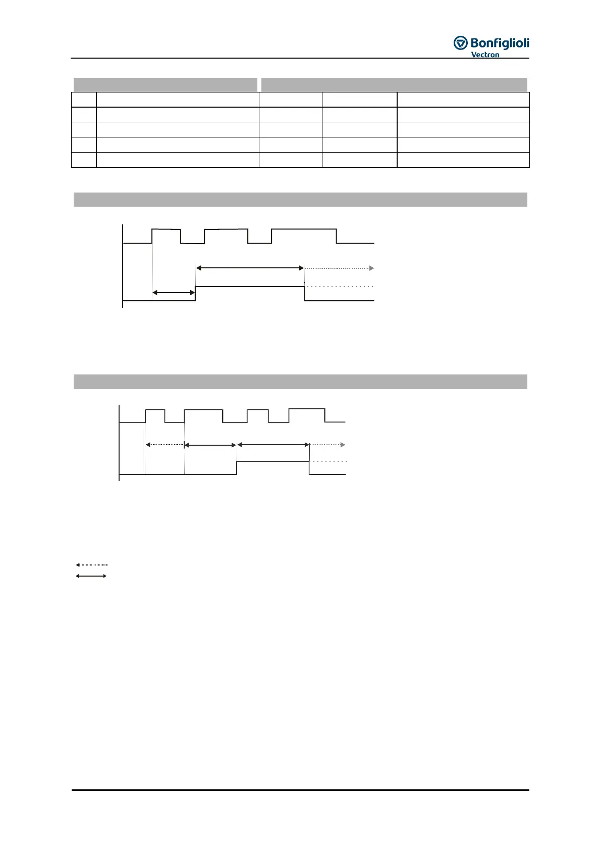
Examples of the timer function depending on the selected operation mode and the input signal:
Parameter Operation Mode Timer 1 790 or Operation Mode Timer 2 793 = 1
As soon as the positive signal edge is received at the input, time 1 is started. Once the Time 1
(signal delay) has elapsed, the output signal will be switched for Time 2 (signal duration).
In the settings for signal duration (Time 2 Timer 1 792 = 0 and Time 2 Timer 2 795 = 0), the
output signal will not be reset.
Parameter Operation Mode Timer 1 790 or Operation Mode Timer 2 793= 2
As soon as the positive signal edge is received at the input, time 1 is started. If a positive signal
edge is detected within the signal delay (Time 1), Time 1 will start again (Retrigger). Once the Time
1 (signal delay) has elapsed, the output signal will be switched for Time 2 (signal duration).
In the settings for signal duration (Time 2 Timer 1 792 = 0 and Time 2 Timer 2 795 = 0), the
output signal will not be reset.
: Time not run out completely
: Time run out completely
Input
Output
Time 2
Time 1
Factory setting (Time 2 = 0)
Input
Output
Time 2Time 1Time 1
Facory setting (Time 2 = 0)