Operating Instructions ACU
13.2 Stopping behavior
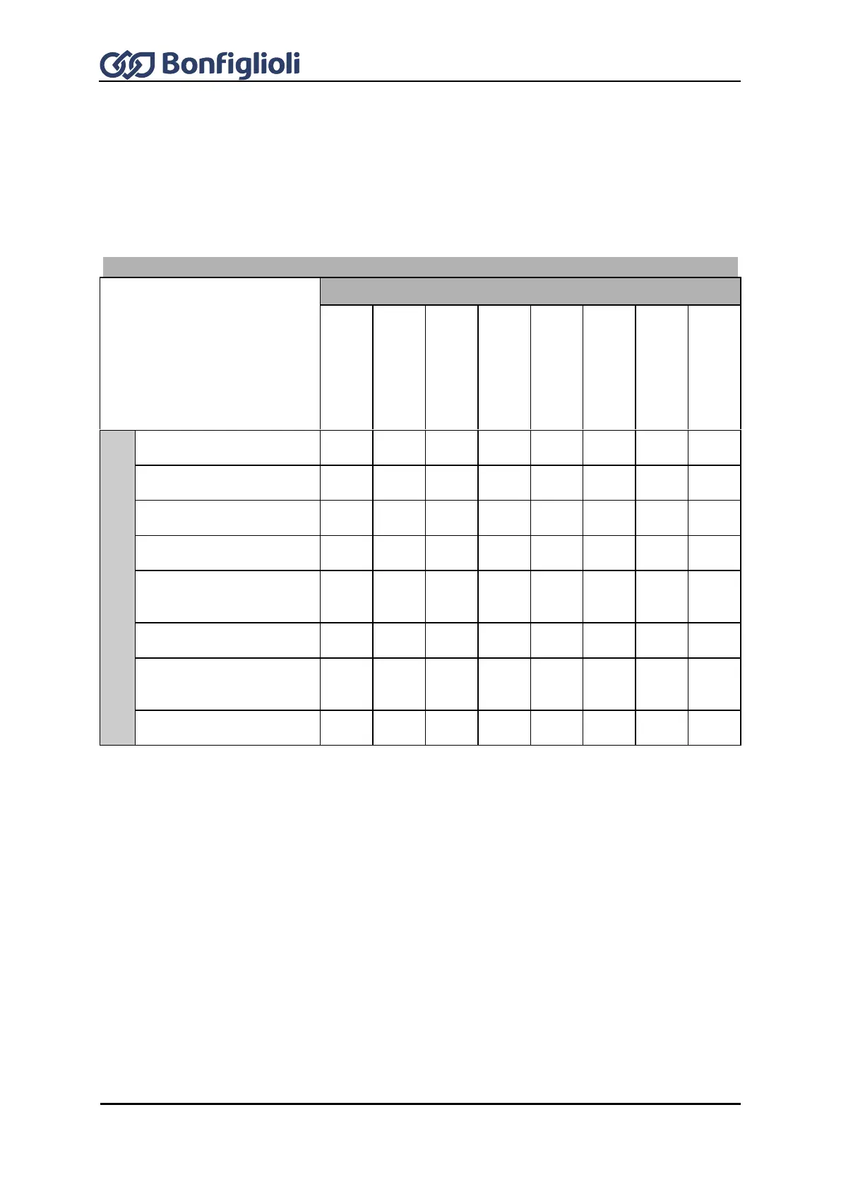
The stopping behavior of the three-phase machine can be defined via parameter Operation
Mode 630. The signal states of the digital inputs or logic signals for parameters Start Clockwise 68
and Start Anticlockwise 69 will activate stopping procedure. Depending on the setting for
Configuration 30, digital inputs or logic signals must be assigned to these parameters or were
already set in the factory. By combination of the digital input states or logic signals, the stopping
behaviors can be selected from the following table.
Start clockwise = 0 and Start anticlockwise = 0
Start clockwise = 1 and Start anticlockwise = 1
Stopping behavior 0
(Coasting)
Stopping behavior 1
(Shutdown and switch off)
Stopping behavior 2
(Shut-down and hold)
Stopping behavior 3
(Shut-down and DC brakes
Stopping behavior 4
(Emergency stop and
switch off)
Stopping behavior 5
(Emergency stop and hold)
Stopping behavior 6
(Emergency stop and DC
brakes)
Stopping behavior 7
(DC brakes)
Operation Mode 630 of the stopping behavior is to be parameterized according to the matrix. The
selection of the operation modes can vary according to the control method and the available control
inputs.
Example: The machine is to stop according to stopping behavior 2 if the digital logic signals Start
Clockwise 68 = 0 and Start Anticlockwise 69 = 0.
Additionally, the machine is to stop according to stopping behavior 1 if the digital logic signals Start
Clockwise 68 = 1 and Start Anticlockwise 69 = 1.
To achieve this, parameter Operation Mode 630 must be set to 12.
By selecting the stopping behavior you also select the control of a mechanical brake if operation
mode „41 - Brake release“ is used for one digital output for controlling the brake.