Operating Instructions ACU
Motion-Block Digital
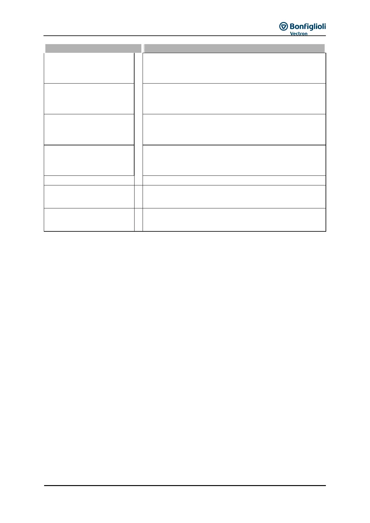
Signal 1
Message on status of a travel order during a positioning
operation. The requirements set for parameter Digital Signal 1
1218 were met. “Start”, “Reference value reached” and “End”
of a motion block were evaluated.
Motion-Block Digital
Signal
Message on status of a travel order during a positioning
operation. The requirements set for parameter Digital Signal 2
1219 were met. “Start”, “Reference value reached” and “End” of
a motion block were evaluated.
Motion-Block Digital
Signal 3
Message on status of a travel order during a positioning
operation. The requirements set for parameter Digital Signal 3
1247 were met. “Start”, “Reference value reached” and “End” of
a motion block were evaluated.
Motion-Block Digital
Signal 4
Message on status of a travel order during a positioning
operation. The requirements set for parameter Digital Signal 4
1248 were met. “Start”, “Reference value reached” and “End” of
a motion block were evaluated.
Operation modes 891 to 894 inverted (LOW active).
Output DeMux bit 0
to
Output DeMux bit 15
Bit 0 to Bit 15 on output of de-multiplexer; de-multiplexed
process data signal via system bus or Profibus on input of
multiplexers (parameter DeMux Input 1253).
FT-output buffer 1
to
FT-output buffer 16
Output signals of FT-instructions of table of functions.
1)
Refer to application manual "Safe Torque Off STO".
2)
Refer to application manual “Positioning”.
3)
Refer to application manual "Safe Torque Off STO".
4)
Refer to operating instructions on extension modules with digital inputs.
5)
The digital signal is independent from the configuration of the parameter Local/Remote 412.
6)
Refer to application manual “Positioning”.
7)
Refer to application manuals "Positioning" and "Electronic Gear".
8)
Refer to operating instructions on extension modules with Profibus.
9)
Refer to application manual “Electronic Gear”.
10)
Refer to operating instructions on extension modules with System Bus.
11)
Refer to operating instructions on extension modules with Profibus interface.
12)
Refer to operating instructions on extension modules with CAN interface.
13)
Refer to application manual “Positioning”.
14)
Refer to operating instructions on extension module with System Bus or Profibus interface.
15)
Refer to application manual “Function Table”.