Operating Instructions ACU
Abs. Actual Percentage
Value
Actual Percentage Value 230 > Maximum Reference
Percentage 519.
Analog Input
MFI1A Abs. value
Analog Input MFI1A 251 > input signal 100%.
Operation modes with signs (+/-).
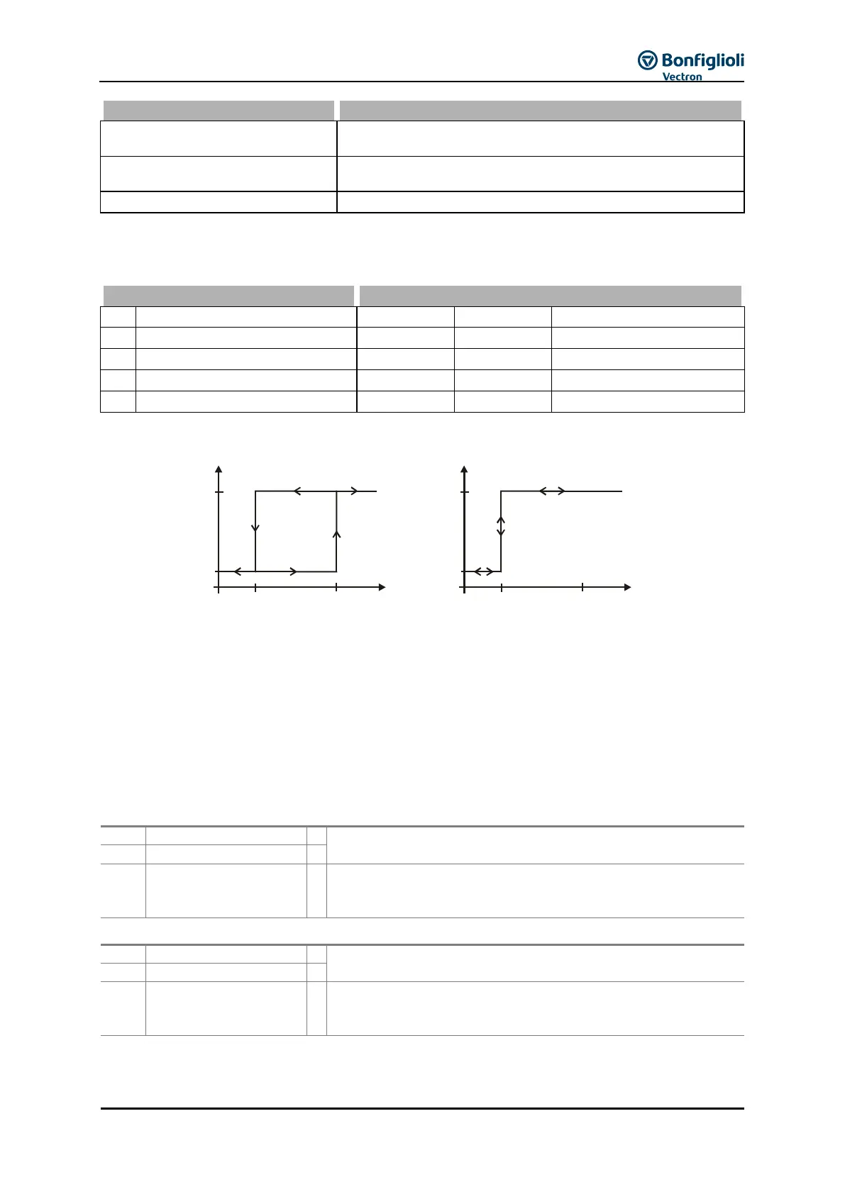
The switch-on and switch-off thresholds for Comparators 1 and 2 are set via parameters Comparator
On above 541, 544 and Comparator Off below 542, 545.
The percentage limits of the corresponding reference values are indicated.
The setting of the percentage limits of the comparators enables the following logical links. The
comparison with signs is possible in the corresponding operation modes of the comparators.
1
on
above
0
off
below
%
1
on
above
0
off
below
%
Example:
Op. Mode Comparator 1 540 = Abs. Actual Frequency
Comparator On above 541 = 80.00 % (referred to Maximum Frequency 419)
Comparator Off below 542 = 50,00 % (referred to Maximum Frequency 419)
Maximum Frequency 419 = 50.00 Hz
Comparator is switched on when Actual Frequency 241 > 40.00 Hz
Comparator is switched off when Actual Frequency 241 > 25.00 Hz
The result of the comparison is reported via digital signals.
The comparison according to the selected Op. Mode
Comparator 1 540 – is true.
Negated Output
Comparator 1
The comparison according to the selected Op. Mode
Comparator 1 540 – is true. The output level of the comparator
is inverted.
The comparison according to the selected Op. Mode
Comparator 2 543 – is true.
Negated Output
Comparator 2
The comparison according to the selected Op. Mode
Comparator 2 543 – is true. The output level of the comparator
is inverted.
1)
For linking to frequency inverter functions
2)
For output via a digital output.