Operating Instructions ACU
The demultiplexer features an input DeMux Input 1253whose signal can be for the process data
RxPDO of the system bus or OUT-PZDx of Profibus.
On the output of the demultiplexer, the logic signals „910 – Output DeMux Bit 0“ to „925 – Output
DeMux Bit15“ are available, e.g. for control of FT-instructions.
Operation Modes for DeMux Input 1253
Remote control word , remote state word
Output DeMux Bit 0 ... output DeMux Bit 15
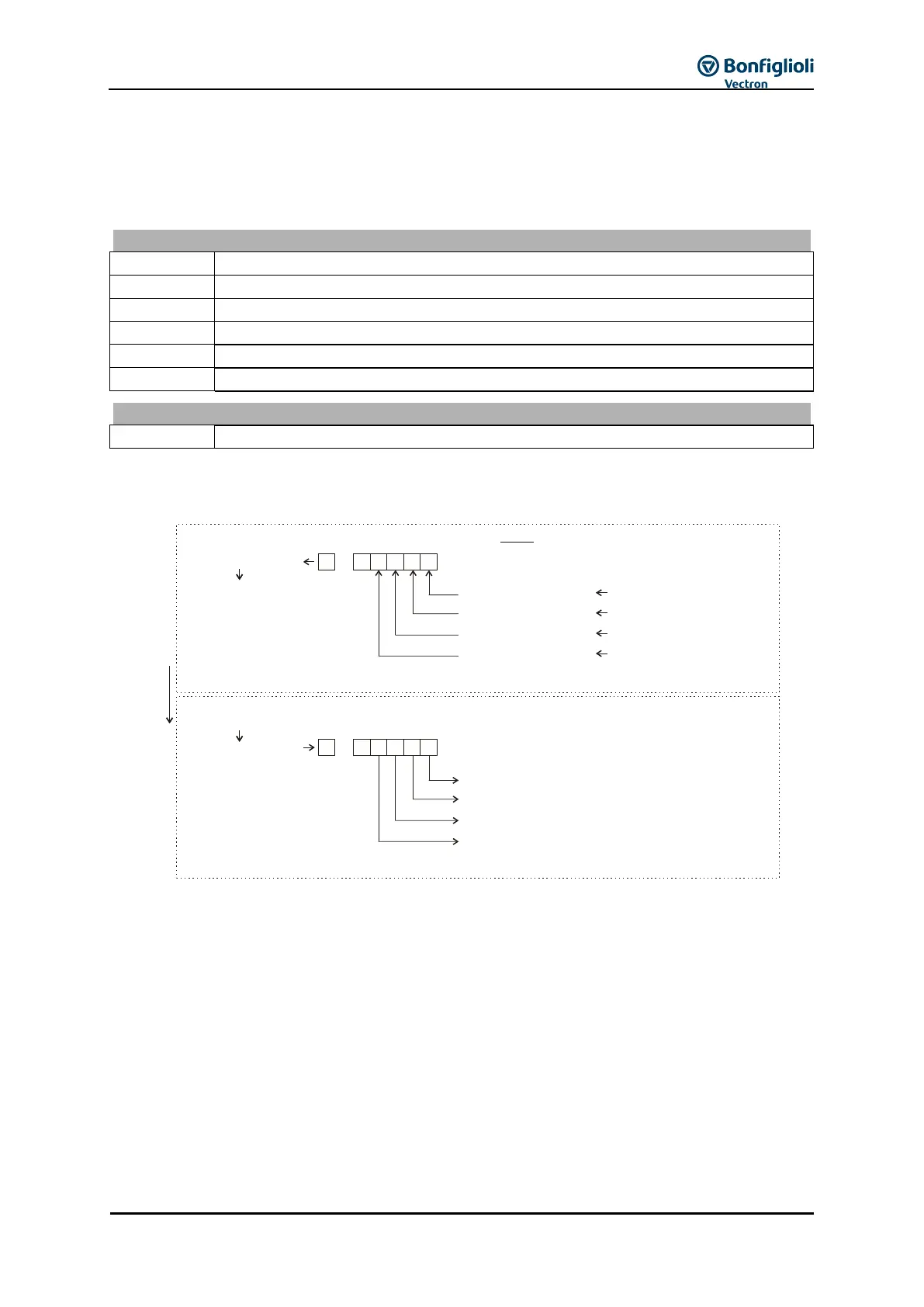
Example: Transfer of a user-defined status word from a slave to a master via system bus or Profibus,
parameterization of multiplexer and demultiplexer using PC application VTable in VPlus
Settings on transmitter:
In VPlus, start application VTable via the button bar.
In VTable assign the required signal sources for sending to parameter Mux Input 1252 index 1 to
index 16. (a setting for index 0 results in this setting being taken over for all other indices.)
Assign signal source „927 – Output MUX“ to a TxPDO process data parameter of the system bus or a
PZDx-IN process data parameter of Profibus.
Settings on receiver:
Assign the corresponding RxPDO signal sources of the system bus or OUT-PZD signal sources of
Profibus to parameter DeMux Input 1253.
The transmitted signals are available at the receiver as signal sources 910 to 925.
User-defined Status word
160 - Standby message
(Standby message)
163 - Reference frequency reached
(Reference frequency reached)
169 - General warning
(General ) warning
162 - Error signal
(Error signal)
Parameter
/Index
Demultiplexer
Systembus: TxPDO1 Word1 950
Mux input /11252
927 - MUX-Output
VTable
Profibus: PZD3_IN Word 1302
0123415
0123415
...
Systembus: 704 - RxPDO1 Word1
DeMux Input 1253
910 - Output DeMux Bit 0
911 - DeMux Bit 1Output
912 - DeMux Bit 2Output
913 - DeMux Bit 3Output
925 - Output DeMux Bit 15
...
Further
Mux 1252 /2input
Mux 1252 /3input
Mux 1252 /4input
...
Further
Profibus: 754 - OUT-PZD3 Word
Receiver
Systembus,
Profibus
Systembus,
Profibus
Transmitter
...
...
Multiplexer
Signal sources
Assign signal sources: