EasyManuals Logo

Bosch B4512 Installation Manual

Bosch B4512
147 pages
To Next Page IconTo Next Page
To Previous Page IconTo Previous Page
Page #129 background imageLoading...
Page #129 background image
Control Panels Specifications | en 129
Bosch Security Systems, Inc. Installation Manual 2018.07 | 16 | F.01U.287.180
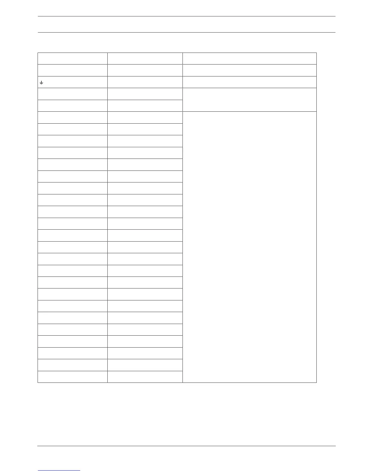
21.1 Wire requirements
Terminal label Terminal description Requirements
18VAC AC 18 AWG to 12 AWG (1.02 mm to 2 mm)
Earth ground 16 AWG to 14 AWG (1.5 mm to 1.8 mm)
BAT + Battery + Bosch supplied wire lead, included with control
panel..
BAT - Battery -
OUTPUT A NO Output A normally open 22 AWG to 12 AWG (0.65 mm to 2 mm)
OUTPUT A C Output A common
OUTPUT A NC Output A normally closed
COM Common
AUX + AUX power
PWR/R SDI2 power
A/Y SDI2 data bus A
B/G SDI2 data bus B
COM/B SDI2 common
1 Point 1
COM Point 1/2 common
2 Point 2
3 Point 3
COM Point 3/4 common
4 Point 4
5 Point 5
COM Point 5/6 common
6 Point 6
7 Point 7
COM Point 7/8 common
8 Point 8
OUTPUT B Output B
OUTPUT C Output C

Table of Contents

Other manuals for Bosch B4512

Questions and Answers:

Question and Answer IconNeed help?

Do you have a question about the Bosch B4512 and is the answer not in the manual?

Bosch B4512 Specifications

General IconGeneral
Control Panel TypeHybrid
Wired Zones8
Outputs2
Programmable Outputs2
Onboard EthernetYes
Cellular CommunicationOptional
SeriesB Series
Partitions2
TypeControl Panel
ModelB4512
ManufacturerBosch
Input Voltage16.5 VAC
Communication FormatsContact ID, SIA
Power Supply16.5 VAC
Backup Battery12 V, 7 Ah
Operating Temperature0°C to +50°C
Weight1.5 kg
CompatibilityBosch accessories

Related product manuals