36 en | IP communications Control Panels
2018.07 | 16 | F.01U.287.180 Installation Manual Bosch Security Systems, Inc.
R
Y
G
B
R
Y
G
B
7 COM 8
C
OUTPUT
B
1 k End of Line Resistors
Voltage Ranges
ON-BOARD POINTS
3.7 - 5.0 VDC
2.0 - 3.0 VDC
0.0 - 1.3 VDC
Open
Normal
Short
3 COM 4 5 COM 61 COM 2
R Y G B
SDI2
Device Bus
AUX
- 12 V +
TMPR
1 COM 2 7 COM 83 COM 4 5 COM 6
RESET
COM AUX
R Y G B
PWR A B COM
B C
OUTPUT
7 COM 8
C
OUTPUT
B
1 k End of Line Resistors
Voltage Ranges
ON-BOARD POINTS
3.7 - 5.0 VDC
2.0 - 3.0 VDC
0.0 - 1.3 VDC
Open
Normal
Short
3 COM 4 5 COM 61 COM 2
R Y G B
SDI2
Device Bus
AUX
- 12 V +
TMPR
1 COM 2 7 COM 83 COM 4 5 COM 6
RESET
COM AUX
R Y G B
PWR A B COM
B C
OUTPUT
3
R
Y
G
B
1
1
2
4
2
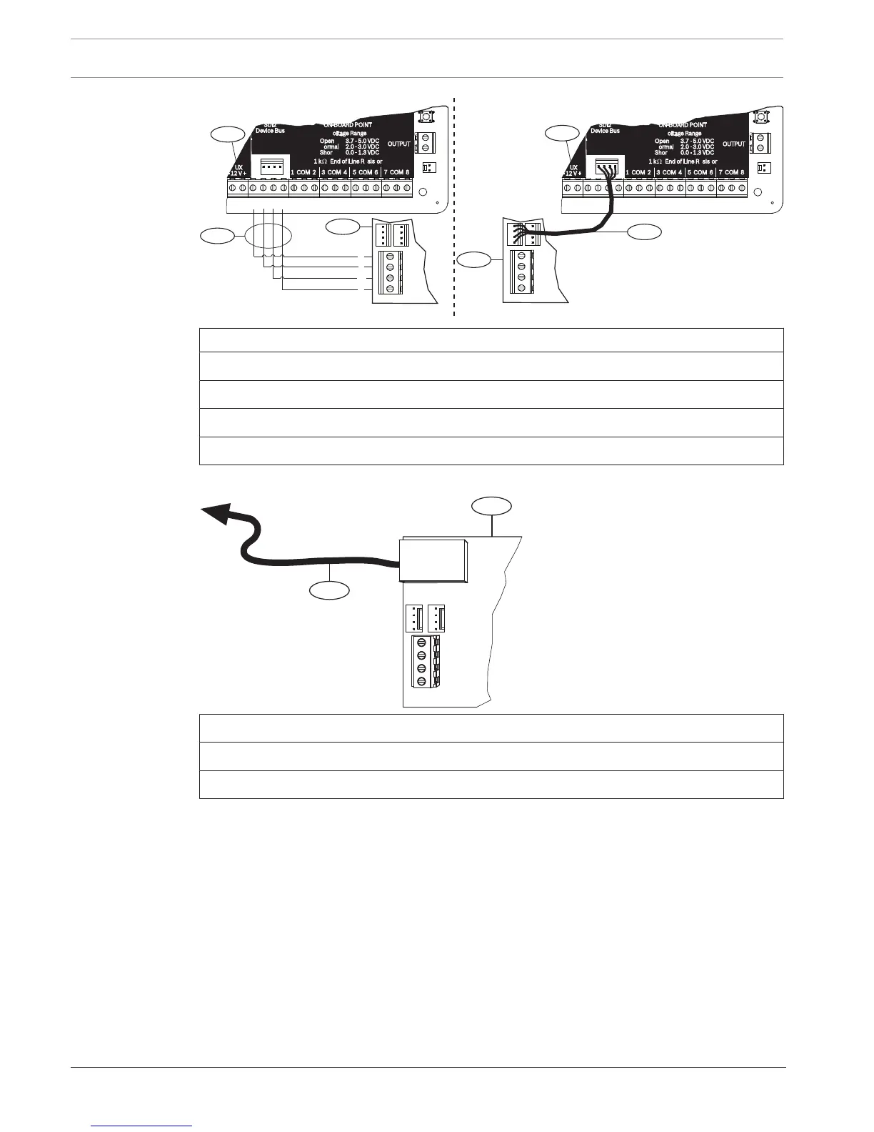
Callout ᅳ Description
1 ᅳ Control panel
2 ᅳ Module
3 ᅳ Terminal strip wiring
4 ᅳ Interconnect cable (P/N: F01U079745) (included)
Connecting the module to the network
Callout ᅳ Description
1 ᅳ B426 module
2 ᅳ Ethernet cable to network jack
1. Connect an Ethernet cable to the Ethernet port on the module.
2. Connect the Ethernet cable to the RJ-45 network jack.
8.3.5 Diagnostic LEDs
The module has the following on-board LEDs to assist with troubleshooting:
– Heartbeat (system status).
– RX (receive).
– TX (transmit).
 Loading...


