Control Panels Keypads, keyswitches, keyfobs and transmitters | en 45
Bosch Security Systems, Inc. Installation Manual 2018.07 | 16 | F.01U.287.180
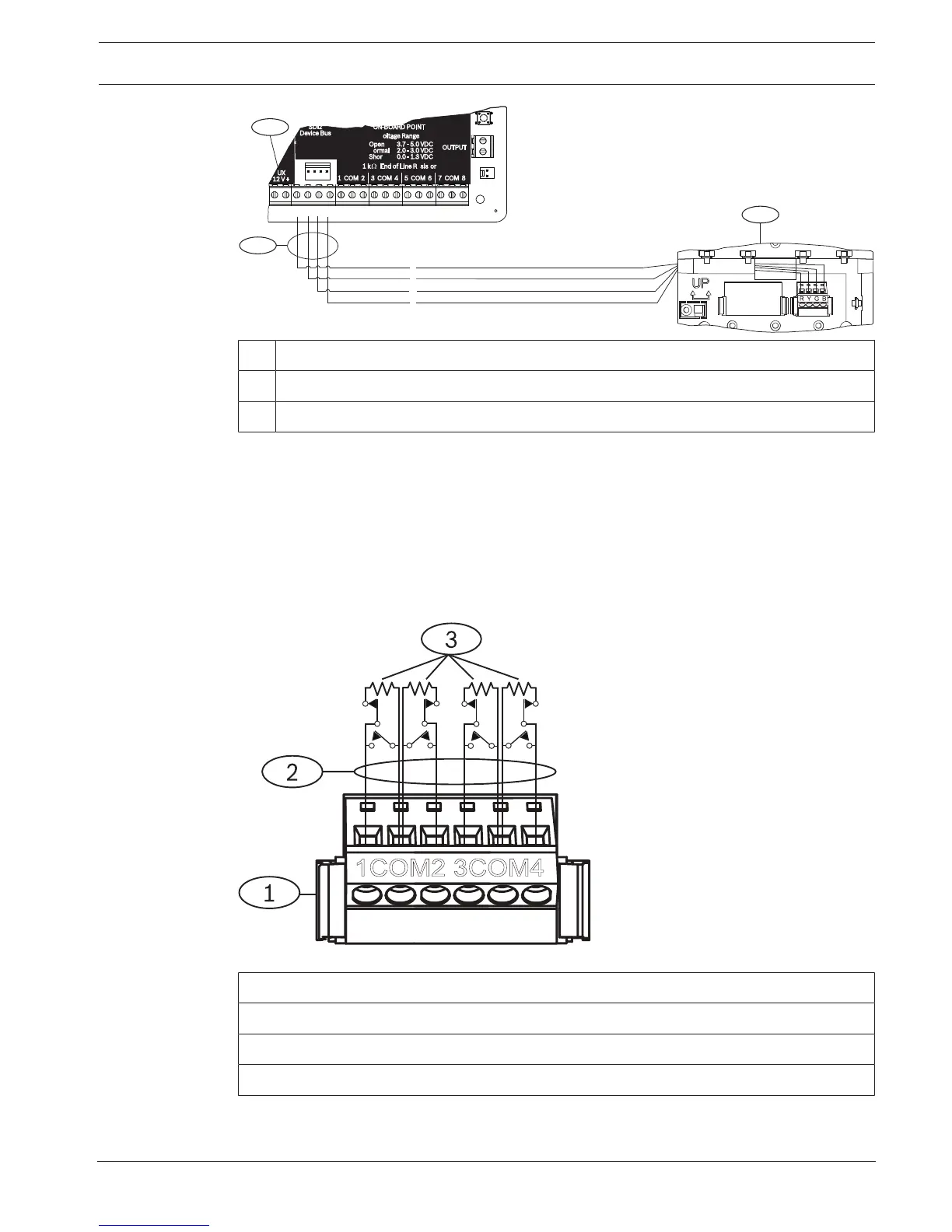
1 Control panel
2 Keypad
3 Terminal strip wiring
9.1.7 Sensor loops overview and wiring (B921C/B942/B942W only)
The keypad detects three states (Open, Supervised, Short) on its sensor loops and sends the
conditions to the control panel. Each sensor loop has an assigned point number.
Use twisted-pair wire for the module sensor loops to avoid electromagnetic interference
problems. Run wires away from the premises telephone and AC wiring.
To wire detection devices to keypad inputs, connect them to the keypad terminals labeled for
COM, and 1, 2, 3, or 4. Wire resistance on each sensor loop must be less than 100 Ω with the
detection devices connected. The terminal strip supports 12 to 22 AWG (0.65 to 2 mm) wires.
Figure9.1: Keypad inputs wiring (B921C shown)
Callout ᅳ Description
1 ᅳ Keypad terminal strip
2 ᅳ Sensor loop
3 ᅳ 1 kΩ EOL resistor (P/N: F01U026703)
 Loading...


