EasyManuals Logo

Bosch B4512 Installation Manual

Bosch B4512
147 pages
To Next Page IconTo Next Page
To Previous Page IconTo Previous Page
Page #55 background imageLoading...
Page #55 background image
Control Panels On-board points | en 55
Bosch Security Systems, Inc. Installation Manual 2018.07 | 16 | F.01U.287.180
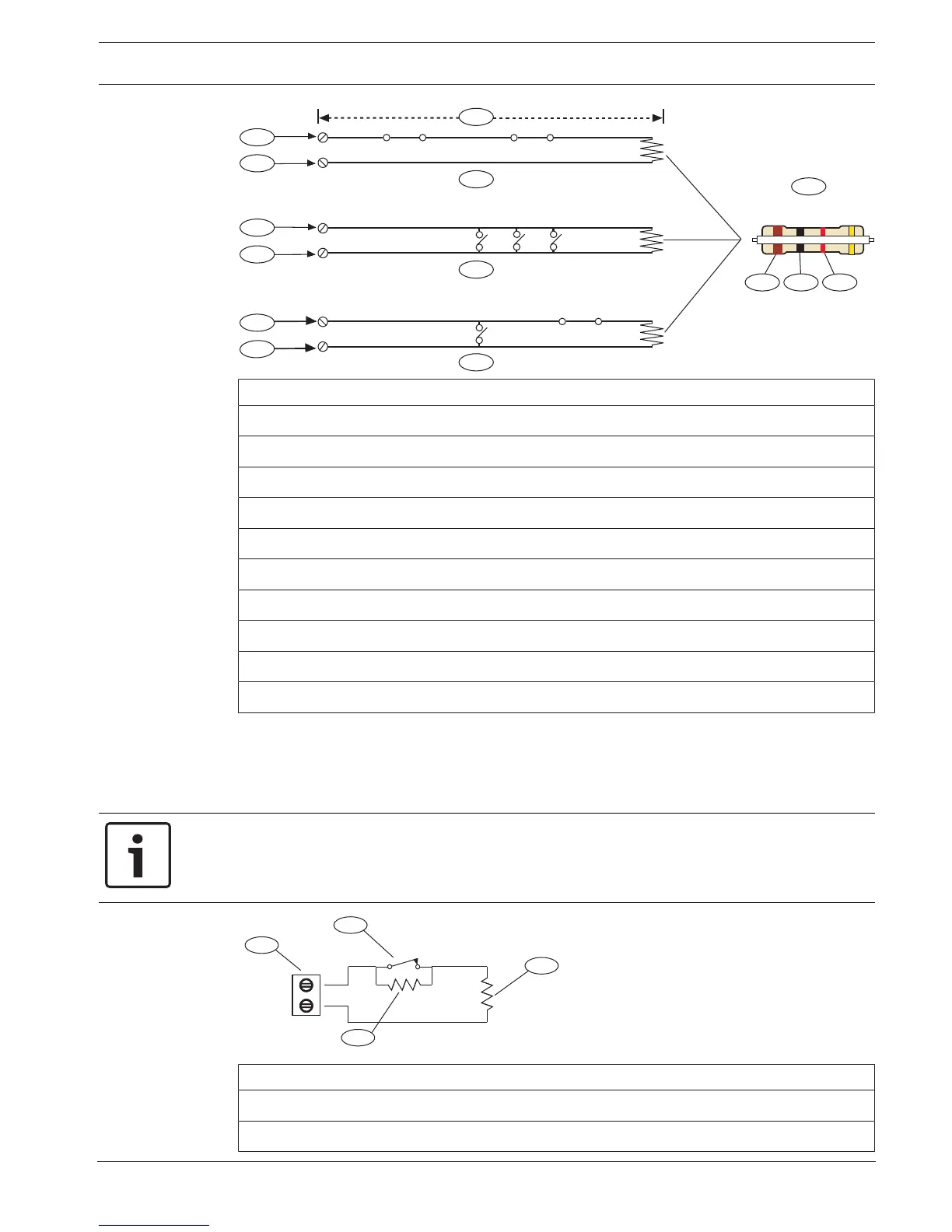
1 kW
8
1
4
5
6
7
2
3
2
3
2
3
9
10
Callout Description
1 100 Ω maximum
2 Point input terminal
3 Common
4 Normally closed contacts (NC)
5 Normally open contacts (NO)
6 Combination: Normally open contacts and normally closed contacts (NO/NC)
7 1 kΩ EOL resistor (ICP-1K22AWG-10)
8 Brown
9 Black
10 Red
Point voltage parameters
Refer to Specifications, page 127.
12.1.2 Dual EOL resistor circuit style
Notice!
EOL resistors
For the dual EOL resistor circuit style order ICP-1K22AWG-10, package of 10 1.0 kΩ EOL
resistors.
Point
COM
NC
1
4
3
2
Callout - Description
1 - Point sensor loop terminals
2 - Normally closed device (contact)

Table of Contents

Other manuals for Bosch B4512

Questions and Answers:

Question and Answer IconNeed help?

Do you have a question about the Bosch B4512 and is the answer not in the manual?

Bosch B4512 Specifications

General IconGeneral
Control Panel TypeHybrid
Wired Zones8
Outputs2
Programmable Outputs2
Onboard EthernetYes
Cellular CommunicationOptional
SeriesB Series
Partitions2
TypeControl Panel
ModelB4512
ManufacturerBosch
Input Voltage16.5 VAC
Communication FormatsContact ID, SIA
Power Supply16.5 VAC
Backup Battery12 V, 7 Ah
Operating Temperature0°C to +50°C
Weight1.5 kg
CompatibilityBosch accessories

Related product manuals