Control Panels System wiring diagrams | en 73
Bosch Security Systems, Inc. Installation Manual 2018.07 | 16 | F.01U.287.180
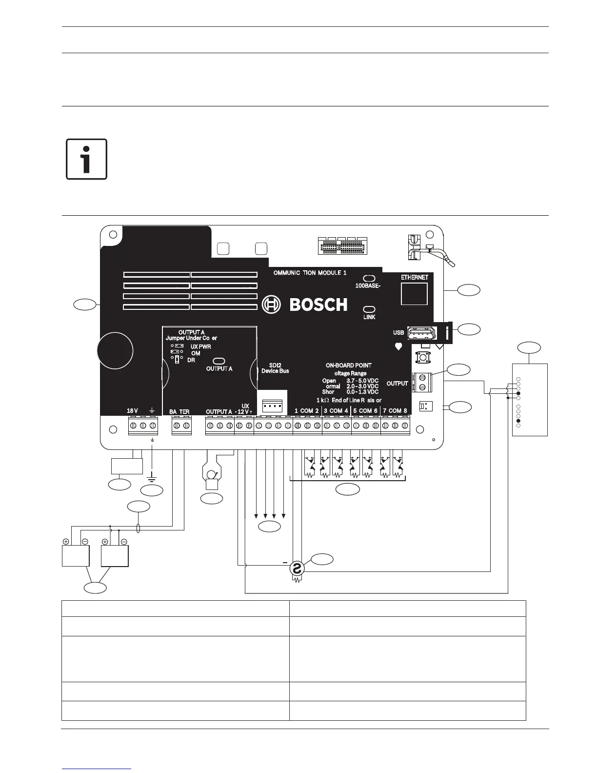
18 System wiring diagrams
18.1 System wiring overview
Notice!
UL Certificated accounts
Additional power can be obtained using only a UL Listed auxiliary 12.0 VDC regulated, power-
limited power supply, such as the B520.
All terminals are power limited except BAT+ (battery positive).
All terminals are supervised except OUTPUT A, OUTPUT B, and OUTPUT C.
For proper supervision, do not loop wire under terminals. Break the wire run to provide
supervision of connections.
Callout ᅳ Description Callout ᅳ Description
1 ᅳ Control panel 8 ᅳ SDI2 wiring
2 ᅳ UL listed class 2 transformer 18 VAC 22 VA 60
Hz (Canada: an ICP-TR1822-CA Plug-in Transformer
120 VAC primary, 18 VAC 22 VA secondary)
9 ᅳ Supervised sensor loops, points 1 to 8 (Initiating
Device Circuits)
3 ᅳ To earth ground 10 ᅳ To ICP-EZTS Tamper Switch
4 ᅳ D122/D122L, as required 11 ᅳ Programmable outputs
 Loading...


