Control Panels Control panel installation | en 17
Bosch Security Systems, Inc. Installation Manual 2018.07 | 16 | F.01U.287.180
5 Control panel installation
Refer to Enclosures, page 86 to determine if the application requires a specific enclosure.
Enclosure overview
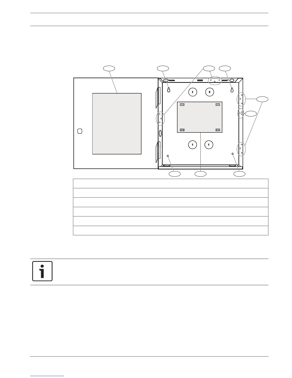
Callout ᅳ Description
1 ᅳ Control panel wiring label
2 ᅳ Enclosure mounting holes (4)
3 ᅳ Three-hole pattern for mounting modules (4)
4 ᅳ Mounting location for the tamper switch
5 ᅳ Mounting location for the control panel
5.1 Installing the enclosure and wiring label
Notice!
Electromagnetic interference (EMI)
EMI can cause problems on long wire runs.
1. Remove the knockouts.
2. Mount the enclosure. Use all enclosure mounting holes. Refer to the mounting
instructions supplied with the selected enclosure.
3. Pull the wires into the enclosure through the knockouts.
4. Position the supplied enclosure wiring label on the inside of the enclosure door.
5.2 Installing the control panel
1. Identify the control panel mounting location in the enclosure.
 Loading...


