52 en | Off-board outputs Control Panels
2018.07 | 16 | F.01U.287.180 Installation Manual Bosch Security Systems, Inc.
11.1.3 Installation and control panel wiring (B308)
Calculate power consumption
Make sure that there is enough power for the module and the other powered devices that you
want to connect to the system.
Refer to On-board outputs, page 49.
Caution!
Remove all power (AC and battery) before making any connections. Failure to do so might
result in personal injury and/or equipment damage.
Notice!
Enclosure
Install the module in the enclosure with the control panel or in an adjacent enclosure that is
within the distances rated for the module: 400 ft (137 m) with 22 AWG (0.6 mm) wire or 1000
ft (305 m) with 18 AWG (1.0 mm) wire.
Installing the module
1. Set the module address.
2. Hold the module mounting brackets onto the inside of the enclosure. Match the bracket
holes to a 3-hole mounting pattern on the enclosure
3. Use the supplied mounting screws to secure the module.
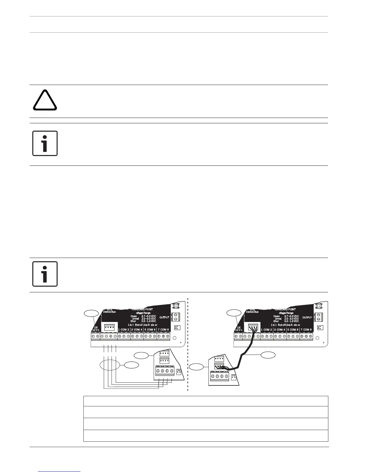
Wiring to the control panel
Use either the terminal strip labeled with PWR, A, B, and COM on the module to wire to the
SDI2 terminals labeled on the control panel, or use the interconnect wiring connector and the
included interconnect cable.
For terminal wiring, use 18 AWG to 22 AWG (1.0 mm to 0.6 mm) wire.
Notice!
Use either the terminal strip wiring or interconnect wiring to the control panel. Do not use
both. When you connect multiple modules, you can combine terminal strip and interconnect
wiring connectors in parallel.
PWR A B COM
7 COM 8
C
OUTPUT
B
1 k End of Line Resistors
Voltage Ranges
ON-BOARD POINTS
3.7 - 5.0 VDC
2.0 - 3.0 VDC
0.0 - 1.3 VDC
Open
Normal
Short
3 COM 4 5 COM 61 COM 2
R Y G B
SDI2
Device Bus
AUX
- 12 V +
TMPR
1 COM 2 7 COM 83 COM 4 5 COM 6
RESET
COM AUX
R Y G B
PWR A B COM
B C
OUTPUT
7 COM 8
C
OUTPUT
B
1 k End of Line Resistors
Voltage Ranges
ON-BOARD POINTS
3.7 - 5.0 VDC
2.0 - 3.0 VDC
0.0 - 1.3 VDC
Open
Normal
Short
3 COM 4 5 COM 61 COM 2
R Y G B
SDI2
Device Bus
AUX
- 12 V +
TMPR
1 COM 2 7 COM 83 COM 4 5 COM 6
RESET
COM AUX
R Y G B
PWR A B COM
B C
OUTPUT
PWR A B COM
2
3
R Y G B
1
1
2
4
 Loading...


