EasyManuals Logo

Bosch B4512 Installation Manual

Bosch B4512
147 pages
To Next Page IconTo Next Page
To Previous Page IconTo Previous Page
Page #74 background imageLoading...
Page #74 background image
74 en | System wiring diagrams Control Panels
2018.07 | 16 | F.01U.287.180 Installation Manual Bosch Security Systems, Inc.
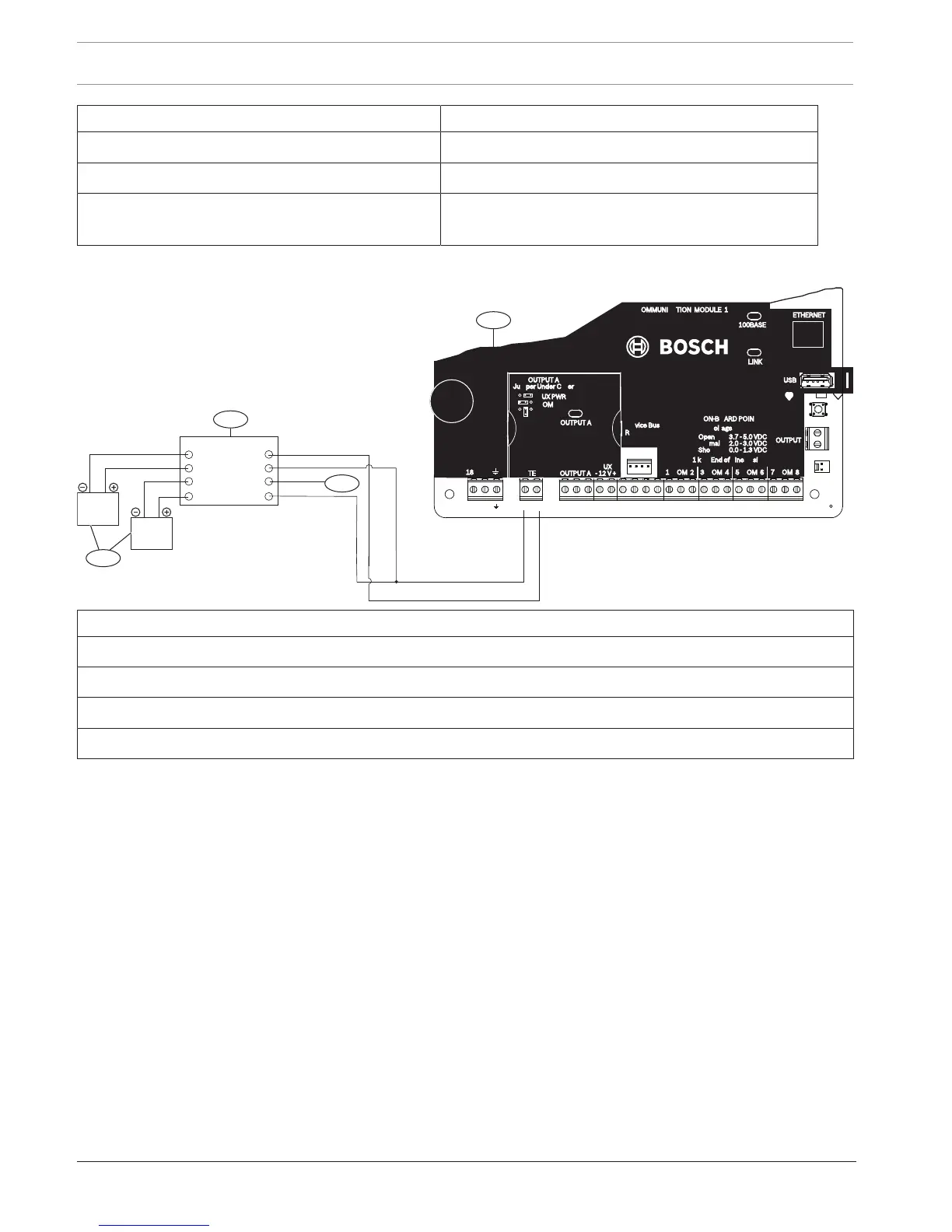
Callout Description Callout Description
5 Batteries (unsupervised) 12 External relay
6 Audible signaling device 13 USB connector
7 UL Listed four-wire smoke detectors with EOL
resistor
14 RJ-45 modular jack for Ethernet (optional)
18.2 Battery lead supervision wiring
1
BAT 2-
BAT 2+
BAT 1-
BAT 1+
CHGR-
VAUX+
SUPV
CHGR+
2
4
3
TMPR
1 COM 2 7 COM 83 COM 4 5 COM 6
RESET
ETHERNET
COM AUX R Y G B
PWR A B COM
+ BAT -18VAC
B C
OUTPUT
NO C NC
OUTPUT A
7 COM 8
C
OUTPUT
B
USB
ETHERNET
100BASE-T
LINK
COMMUNICATION MODULE 1
1 k End of Line Resistors
Voltage Ranges
ON-BOARD POINTS
3.7 - 5.0 VDC
2.0 - 3.0 VDC
0.0 - 1.3 VDC
Open
Normal
Short
3 COM 4 5 COM 61 COM 2
R Y G B
SDI2
Device Bus
18 VAC
BATTERY OUTPUT A
AUX
- 12 V +
OUTPUT A
OUTPUT A
Jumper Under Cover
AUX PWR
COM
DRY
Callout Description
1 D113 Supervision module, battery lead, if required
2 Batteries
3 To supervision point
4 Control panel

Table of Contents

Other manuals for Bosch B4512

Questions and Answers:

Question and Answer IconNeed help?

Do you have a question about the Bosch B4512 and is the answer not in the manual?

Bosch B4512 Specifications

General IconGeneral
Control Panel TypeHybrid
Wired Zones8
Outputs2
Programmable Outputs2
Onboard EthernetYes
Cellular CommunicationOptional
SeriesB Series
Partitions2
TypeControl Panel
ModelB4512
ManufacturerBosch
Input Voltage16.5 VAC
Communication FormatsContact ID, SIA
Power Supply16.5 VAC
Backup Battery12 V, 7 Ah
Operating Temperature0°C to +50°C
Weight1.5 kg
CompatibilityBosch accessories

Related product manuals