54 en | On-board points Control Panels
2018.07 | 16 | F.01U.287.180 Installation Manual Bosch Security Systems, Inc.
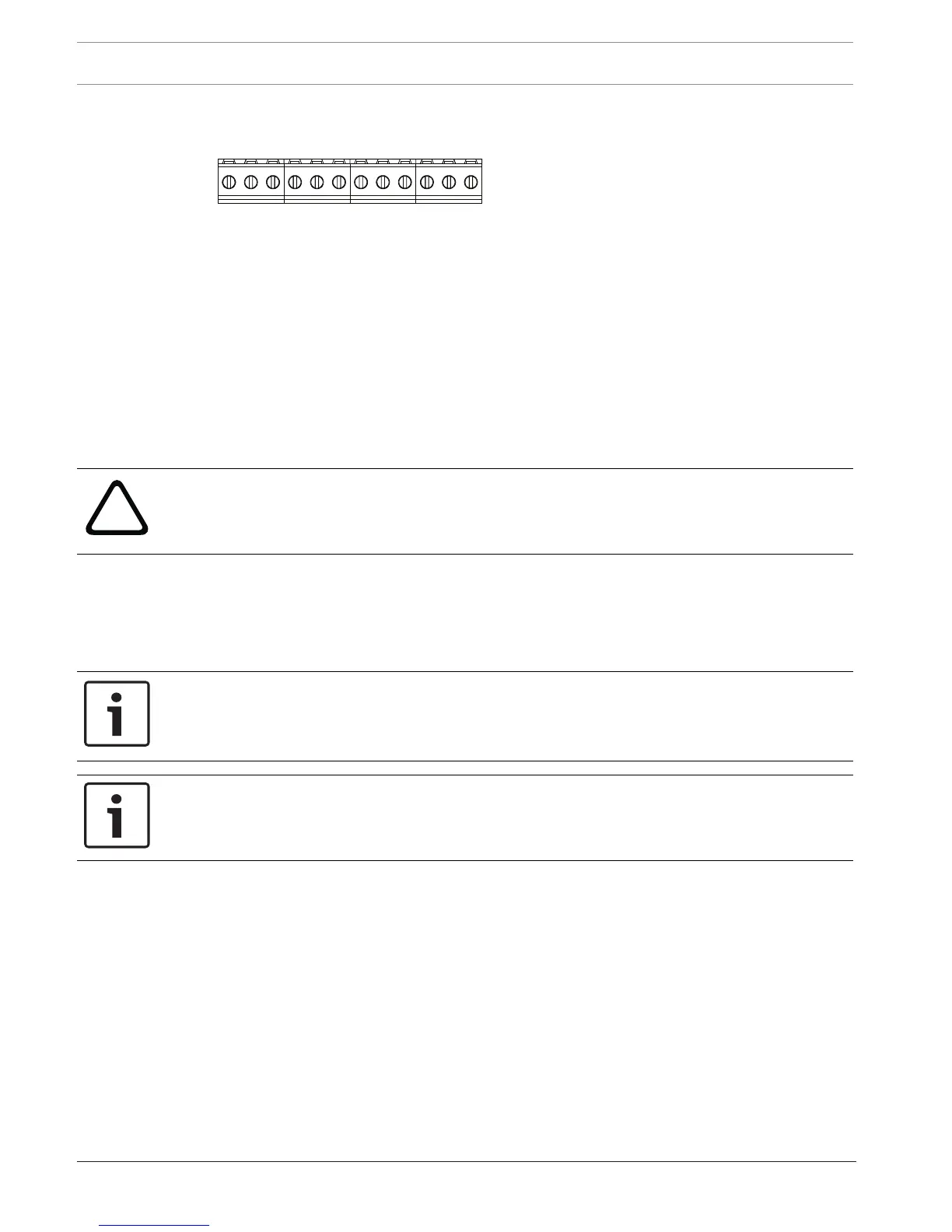
12 On-board points
The control panel provides eight on-board points . Each point functions independently and
does not interfere with the operation of the others. The control panel monitors the sensor
loops for the following conditions between an input terminal and any of the point common
terminals:
– Normal
– Shorted
– Open
The programming for the point determines how the control panel responds to those
conditions.
The control panel ignores sensor loops (both on-board and off-board) for 60 seconds after
power up to make sure that any connected devices stabilize.
Caution!
Points programmed as fire supervisory points are latching. A latching point requires that you
acknowledge it before you can clear it.
12.1 Point sensor loops
You can configure each sensor loop for a single EOL resistor, or for dual EOL resistors. Single
EOL resistor is the default. For dual EOL resistors, set the Point Profile > Circuit Style
parameter to dual.
Notice!
You do not need to install the EOL resistor for unused points (Point Profile parameter set to 0
[zero]).
UL does not permit normally closed loops for commercial fire applications.
Notice!
Optionally use these points for household fire applications. You can connect four-wire
detectors to these points, for example.
12.1.1 Single EOL (and no EOL) resistor circuit style
For the single EOL resistor circuit style, install the resistor at the far end of the sensor loop to
provide a reference for supervision. You can connect dry contact sensing devices in series
(normally closed) or in parallel (normally open) to any of these loops.
The number of normally open and normally closed detection devices each sensor loop can
supervise is limited only by the resistance on the loop. The total resistance for the wire length
and contacts, excluding the end-of-line (EOL) resistor, must not exceed 100 Ω.
 Loading...


