Control Panels IP communications | en 33
Bosch Security Systems, Inc. Installation Manual 2018.07 | 16 | F.01U.287.180
2. Connect the control panel to the RPS or Installer Services Portal programming tool
computer using the Ethernet ports and a standard Ethernet cable, and apply power to the
control panel, if applicable. Within 2 minutes, the RPS or Installer Services Portal
programming tool computer assigns an IP address using AutoIP.
3. In RPS or the Installer Services Portal programming tool, open the control panel account
and click the Connect button. From the Connect Via drop-down list select IP Direct. Click
Connect. Once connected, perform the necessary tasks, and disconnect when finished.
4. Reconnect the cable used for IP communication, if applicable.
For more information on using AutoIP, refer to AutoIP, page 144.
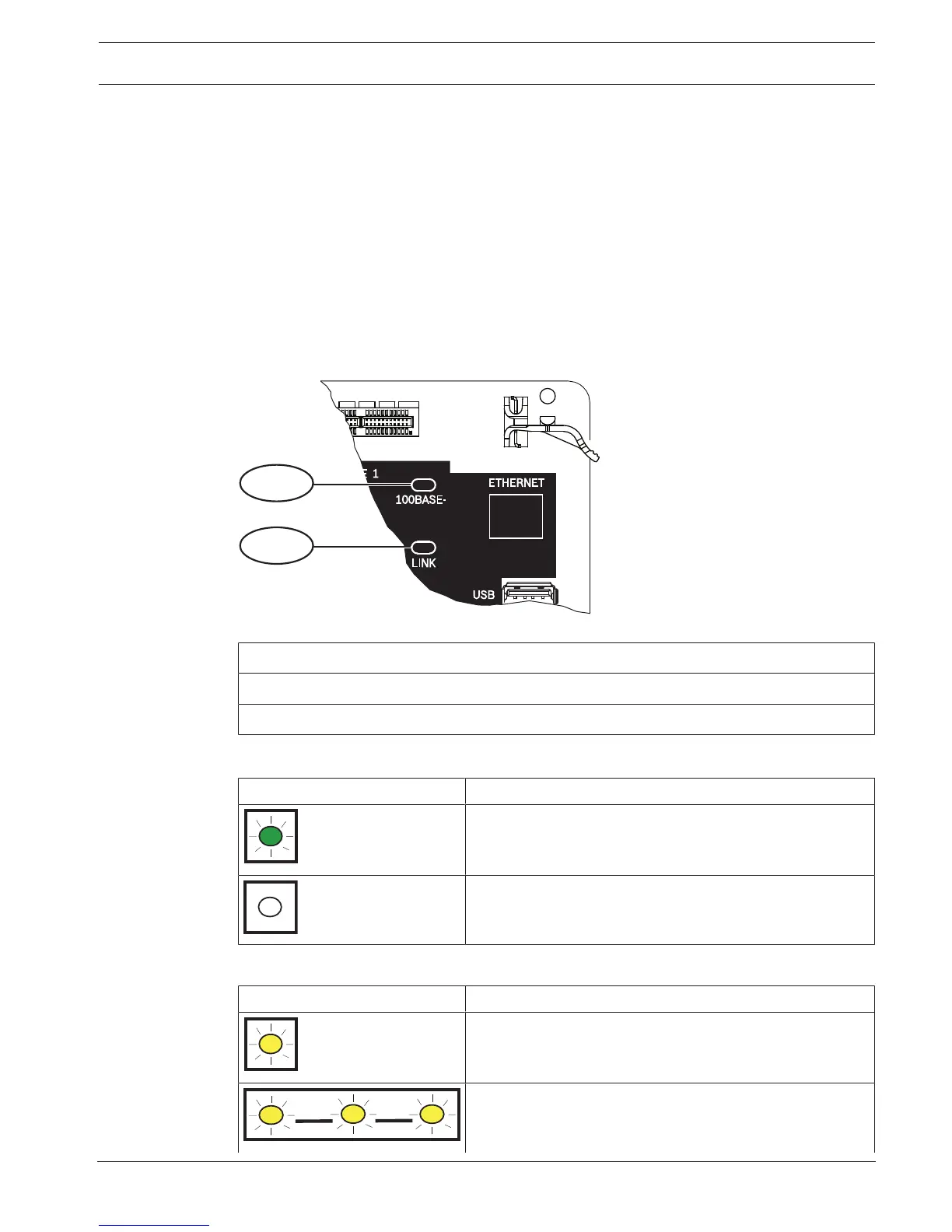
8.1.3 On-board Ethernet diagnostic LEDs
The control panel includes the following on-board LEDs to assist with troubleshooting the on-
board Ethernet connection.
Figure8.1: On-board Ethernet and LEDs (B5512 shown)
Callout ᅳ Description
1 ᅳ 100BASE-T LED (green)
2 ᅳ LINK LED (yellow)
Refer to the following tables for information on the 100BASE-T and LINK LEDs.
Flash pattern Function
On Steady
Communicating at 100 Mb.
Off
Communicating at 10 Mb.
Tab.8.2: 100BASE-T LED descriptions
Flash pattern Function
On Steady
Plugged into an Ethernet network.
Communication in progress.
 Loading...


