Control Panels Wireless modules | en 63
Bosch Security Systems, Inc. Installation Manual 2018.07 | 16 | F.01U.287.180
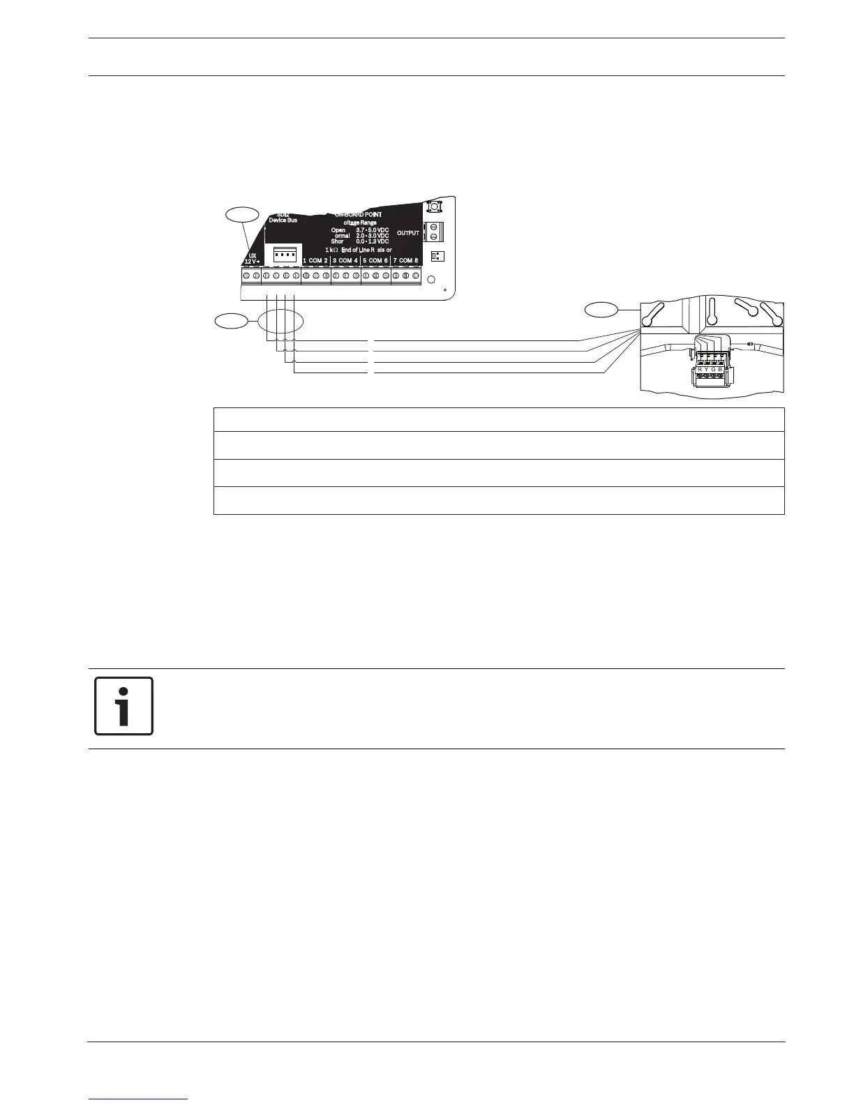
Wiring to the control panel
Use the terminal strip labeled with PWR, A, B, and COM on the module to wire to the SDI2
terminals labeled on the control panel. Wire the module within the distances rated for the
module: 600 ft. (183 m) with 22 AWG (0.6 mm) wire or 1000 ft. (305 m) with 18 AWG (1.0
mm) wire.
Callout ᅳ Description
1 ᅳ Control panel
2 ᅳ Module
3 ᅳ Terminal strip wiring
14.2 B820 SDI2 Inovonics Interface Module
The B820 is a module to connect a control panel with an Inovonics EN4200 EchoStream Serial
Receiver.
For detailed instructions, refer to the corresponding document listed in Related
documentation, page 12.
14.2.1 SDI2 address settings
Notice!
The module reads the address switch setting only during module power up. If you change the
setting after you apply power to the module, you must cycle the power to the module in order
for the new setting to take effect.
The control panel supports only address 1.
14.2.2 Supervision
The control panel enables supervision of the module when you enroll at least one RF device.
Available RF devices on the control panel include RF Repeaters, wireless points, or user
keyfobs. Any failure to receive an expected response from an SDI2 module results in a system
fault display on all keypads and a fault event sent to the central station.
14.2.3 Installation and control panel wiring (B820)
Calculate power consumption
Make sure that there is enough power for the module and the other powered devices that you
want to connect to the system.
Refer to On-board outputs, page 49.
 Loading...


