EasyManuals Logo

Bosch B4512 Installation Manual

Bosch B4512
147 pages
To Next Page IconTo Next Page
To Previous Page IconTo Previous Page
Page #64 background imageLoading...
Page #64 background image
64 en | Wireless modules Control Panels
2018.07 | 16 | F.01U.287.180 Installation Manual Bosch Security Systems, Inc.
!
Caution!
Remove all power (AC and battery) before making any connections. Failure to do so might
result in personal injury and/or equipment damage.
Installing the module
1. Set the module address using the address switch before you install it in the EN4200
housing.
2. Use the address switch to set the module address.
3. Use a slotted screwdriver to press the housing release tabs and open the housing.
4. Remove the backing from one side of the supplied Velcro piece to show the Velcro
adhesive.
5. Put the adhesive side of the Velcro onto the back of the module.
6. Remove the other backing from the Velcro.
7. Insert the module into the housing.
8. Connect the serial ports on the B820 and EN4200.
9. Push gently on the B820 to make sure that the Velcro sticks.
10. Refer to the EN4200 EchoStream Serial Receiver Installation Instructions for mounting and
wiring instructions for the receiver.
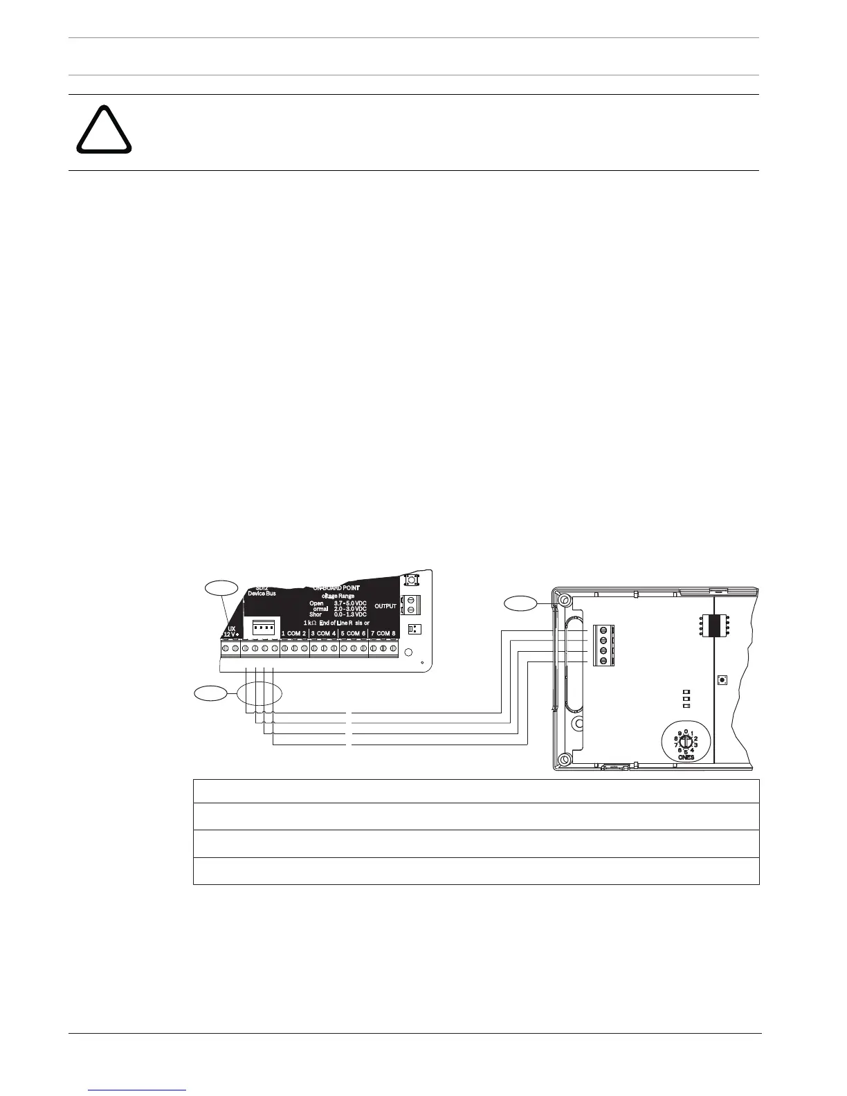
Wiring to the control panel
Use the terminal strip labeled with PWR, A, B, and COM on the module to wire to the SDI2
terminals labeled on the control panel. Wire the module within the distances rated for the
module: 600 ft. (183 m) with 22 AWG (0.6 mm) wire or 1000 ft. (305 m) with 18 AWG (1.0
mm) wire.
Route the cabling through the control panel enclosure, and through the EN4200 housing.
PWR A B COM
1
2
3
R
Y
G
B
7 COM 8
C
OUTPUT
B
1 k End of Line Resistors
Voltage Ranges
ON-BOARD POINTS
3.7 - 5.0 VDC
2.0 - 3.0 VDC
0.0 - 1.3 VDC
Open
Normal
Short
3 COM 4 5 COM 61 COM 2
R Y G B
SDI2
Device Bus
AUX
- 12 V +
TMPR
1 COM 2 7 COM 83 COM 4 5 COM 6
RESET
COM AUX
R Y G B
PWR A B COM
B C
OUTPUT
Callout Description
1 Control panel
2 Module
3 Terminal strip wiring

Table of Contents

Other manuals for Bosch B4512

Questions and Answers:

Question and Answer IconNeed help?

Do you have a question about the Bosch B4512 and is the answer not in the manual?

Bosch B4512 Specifications

General IconGeneral
Control Panel TypeHybrid
Wired Zones8
Outputs2
Programmable Outputs2
Onboard EthernetYes
Cellular CommunicationOptional
SeriesB Series
Partitions2
TypeControl Panel
ModelB4512
ManufacturerBosch
Input Voltage16.5 VAC
Communication FormatsContact ID, SIA
Power Supply16.5 VAC
Backup Battery12 V, 7 Ah
Operating Temperature0°C to +50°C
Weight1.5 kg
CompatibilityBosch accessories

Related product manuals