Control Panels Control panel installation | en 19
Bosch Security Systems, Inc. Installation Manual 2018.07 | 16 | F.01U.287.180
5.2.1 Earth ground
To help prevent damage from electrostatic discharges or other transient electrical surges,
connect the system to earth ground before making other connections. The earth ground icon
identifies the earth ground terminal. Recommended earth ground references are a grounding
rod or a cold water pipe. Make the connection using 14 AWG (1.8 mm) to 16 AWG (1.5 mm)
wire.
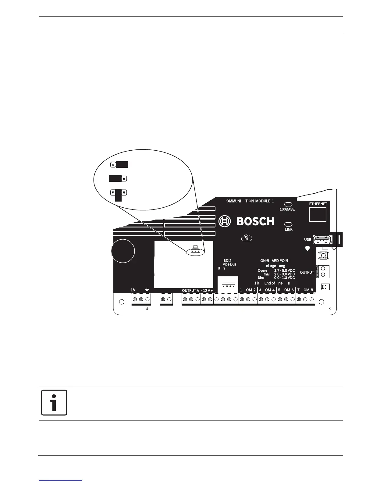
5.2.2 OUTPUT A jumper
OUTPUT A is a form C relay. Choose one of the following uses before you install and configure
OUTPUT A:
– +12 VDC (AUX power)
– COM terminal (parallel to all COM terminals)
– Dry contact (no voltage, not common)
P1
P1
P1
OUTPUT A (C terminal) = AUX PWR
COM AUX
OUTPUT A (C terminal) = COM
OUTPUT A (C terminal) = DRY
COM AUX
COM AUX
COM AUX
P1
TMPR
1 COM 2 7 COM 83 COM 4 5 COM 6
RESET
ETHERNET
COM AUX R Y G B
PWR A B COM
+ BAT -18VAC
B C
OUTPUT
NO C NC
OUTPUT A
7 COM 8
C
OUTPUT
B
USB
ETHERNET
100BASE-T
LINK
COMMUNICATION MODULE 1
1 k End of Line Resistors
Voltage Ranges
ON-BOARD POINTS
3.7 - 5.0 VDC
2.0 - 3.0 VDC
0.0 - 1.3 VDC
Open
Normal
Short
3 COM 4 5 COM 61 COM 2
R Y G B
SDI2
Device Bus
18 VAC
OUTPUT A
AUX
- 12 V +
The control panel ships with the jumper in the default position, AUX power. (OUTPUT A, ‘C’
terminal providing AUX PWR). To reconfigure the ‘C’ terminal as a COM terminal (parallel to all
COM terminals), remove the door covering the jumper pins, and move the jumper to the left
two pins. The OUTPUT A LED lights when OUTPUT A is active.
5.3 Control panel to module wiring overview
You can use interconnect or terminal wiring to connect devices to the control panel.
Using terminal wiring in parallel
Notice!
Wire size
For terminal wiring, use 18 AWG to 22 AWG (1.0 mm to 0.6 mm) wire.
 Loading...


