18 en | Control panel installation Control Panels
2018.07 | 16 | F.01U.287.180 Installation Manual Bosch Security Systems, Inc.
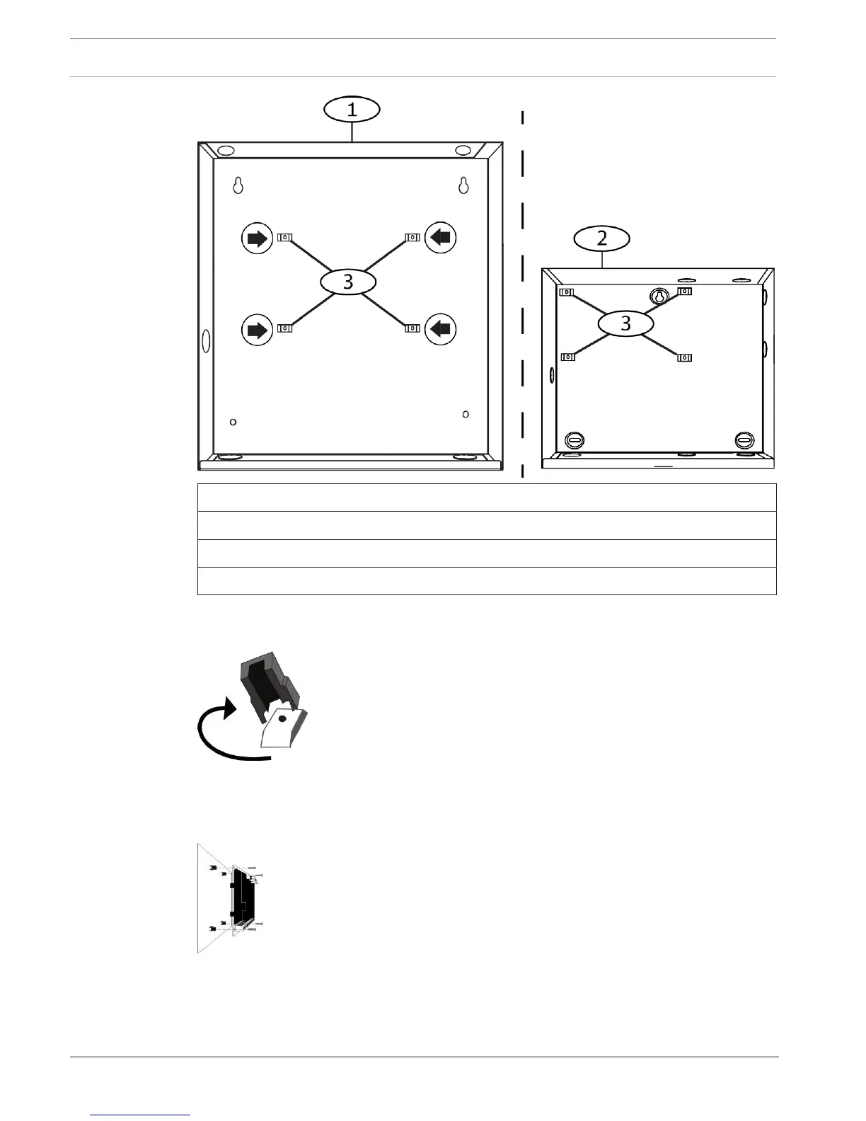
Callout ᅳ Description
1 ᅳ B10 Medium Control Panel Enclosure
2 ᅳ B11 Small Control Panel Enclosure
3 ᅳ Mounting clip locations for the control panel
2. Snap the four plastic standoffs onto the four enclosure support posts. If you install a B12,
attach the standoffs to the plate support posts. Do not attach the standoff screws.
3. Position the control panel on top of the standoffs.
4. Align the holes in the corners of the control panel with the openings at the top of each
standoff.
5. Attach and tighten the control panel to the standoffs with the supplied screws.
6. If you install a B12, rest the hook tabs on the mounting plate hooks within the enclosure.
Secure the lock-down tab to the plate mounting hole with the screw provided.
 Loading...


