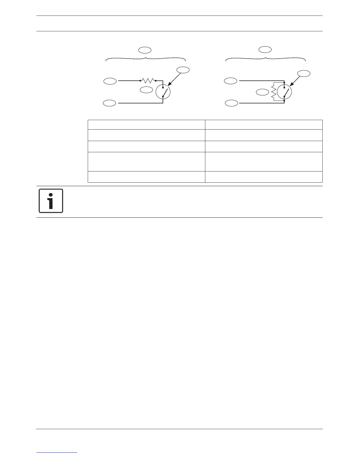
Callout ᅳ Description Callout ᅳ Description
1 ᅳ Maintained keyswitch 5 ᅳ EOL (End of Line) resistor
2 ᅳ Momentary keyswitch 6 ᅳ Open on the circuit arms the area
3 ᅳ Common 7 ᅳ Momentary short on the circuit toggles
the arming state
4 ᅳ Point input
Notice!
UL requirement
Keyswitches are not intended for use in UL listed systems.
9.3 RADION keyfobs and Inovonics pendant transmitters
The control panel supports one RADION keyfob or one Inovonics pendant transmitter for each
user the control panel supports.
– B6512. Up to 10 wireless RADION keyfobs or 100 Inovonics pendant transmitters.
– B5512. Up to 50 wireless RADION keyfobs or 50 Inovonics pendant transmitters.
– B4512. Up to 32 wireless RADION keyfobs or 32 Inovonics pendant transmitters.
– B3512. Up to 10 wireless RADION keyfobs or 10 Inovonics pendant transmitters.
The control panel supports two RADION keyfob models, RFKF-FB-A and RFKF-TB-A, that
communicate with the control panel using the B810 wireless receiver.
RADION keyfob FB
The RADION keyfob FB four button keyfobs are designed for arming (lock icon) and disarming
(unlock icon) the system remotely. You can configure the programmable buttons at the control
panel for additional control functionality. To operate the programmable buttons, simply press
and hold either button for at least one sec in order for the desired feature to work.
– Uniquely coded arm and disarm buttons
– Panic alarm
– LED indicator
– Programmable option buttons
RADION keyfob TB
The RADION keyfob TB two button keyfobs are designed for arming (lock icon) and disarming
(unlock icon) the system remotely. To operate these buttons, simply press and hold either
button for at least one sec in order for the desired feature to work.
– Uniquely coded arm and disarm buttons
– Panic alarm
– LED indicator
 Loading...


