76 en | System wiring diagrams Control Panels
2018.07 | 16 | F.01U.287.180 Installation Manual Bosch Security Systems, Inc.
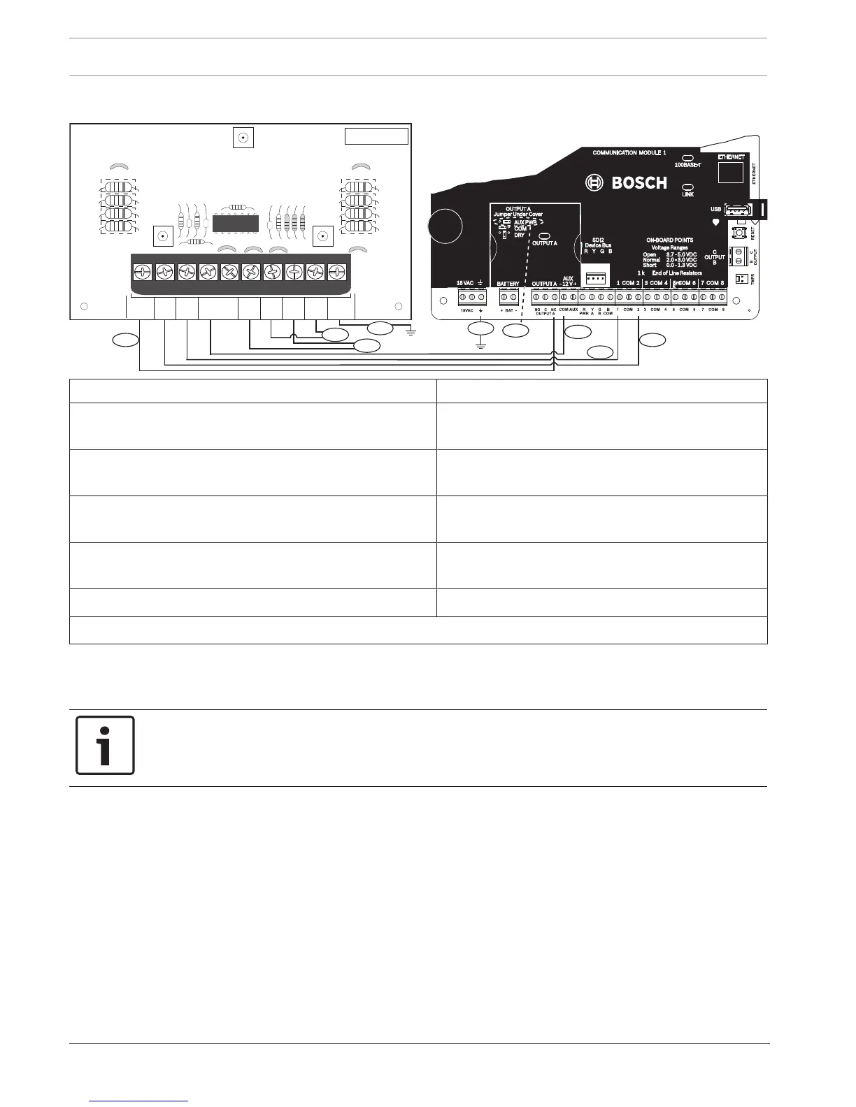
18.4 2-wire smoke wiring (D125B)
Callout ᅳ Description Callout ᅳ Description
1 ᅳ Switched auxiliary power from Output A (NC)
1 of
of the
control panel
7 ᅳ Supervised smoke detector to A LOOP negative
2 ᅳ Connection from an on-board point on the control
panel to Zone B
8 ᅳ Supervised smoke detector to B LOOP positive
3 ᅳ Connection from an on-board point on the control
panel to Zone A
9 ᅳ Supervised smoke detector to A LOOP positive
4/5 ᅳ Connection to common on the control panel (one
connection only)
10 ᅳ Earth ground
6 ᅳ Supervised smoke detector to B LOOP negative 11 ᅳ Output A jumper (under cover) set to AUX PWR
1
You can also use Output B or C in conjunction with a D133 or D134 relay module.
18.5 Notification appliance circuit wiring
The control panel does not have an on-board NAC. For systems requiring a NAC, use a D192G.
Notice!
UL requirement
For UL Listed fire alarm applications, install a D192G.
For detailed instructions, refer to the corresponding document listed in Related
documentation, page 12.
 Loading...


