Control Panels Telephone communications | en 29
Bosch Security Systems, Inc. Installation Manual 2018.07 | 16 | F.01U.287.180
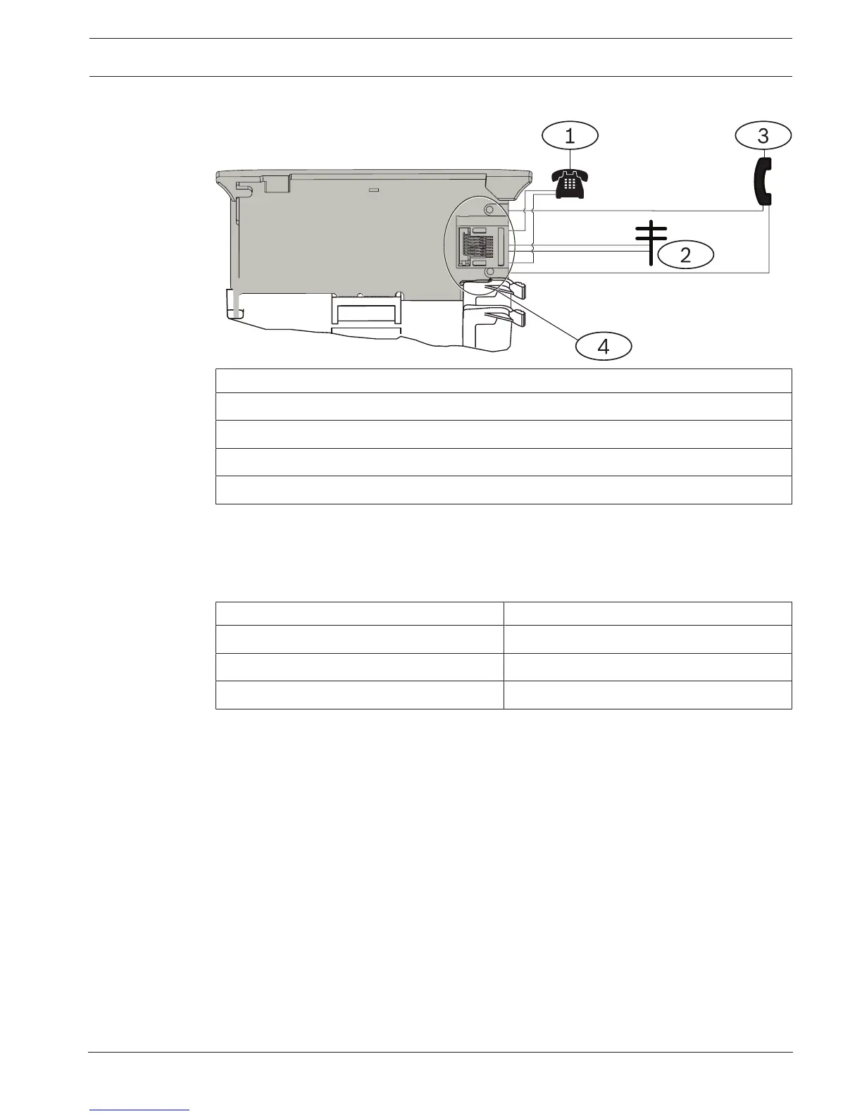
Wiring to the phone line
Callout ᅳ Description
1 ᅳ Premises telephone
2 ᅳ Incoming Telco line
3 ᅳ Installer telephone test set
4 ᅳ RJ-45 phone connector
7.1.3 Diagnostic LEDs
The module uses a green LED to show:
– Whether the module is on or off hook.
– When the line rings (incoming phone call).
Flash pattern Function
OFF Standby
ON Line seized
Flash Ringing detect (incoming phone call)
Tab.7.1: PTSN diagnostic LED patterns
7.2 Phone jack location
To prevent jamming of signals, wire the RJ31X or RJ38X jack before the premises telephone
system to support line seizure. Install the jack on the street side of the telephone switch,
wired ahead of any PBX equipment. Line seizure temporarily interrupts normal telephone use
while the control panel sends data. After installation, make sure that the control panel:
– Seizes the line
– Gets a dial tone
– Reports correctly to the receiver
– Releases the telephone line to the in-house telephone system
 Loading...


