78 en | System wiring diagrams Control Panels
2018.07 | 16 | F.01U.287.180 Installation Manual Bosch Security Systems, Inc.
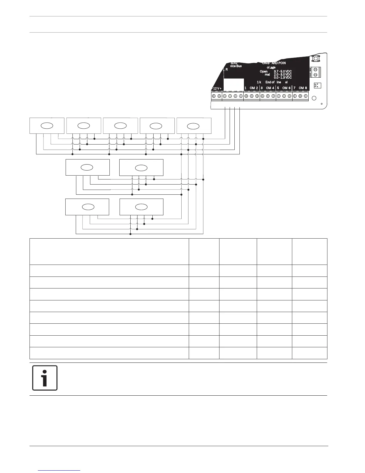
18.6 SDI2 devices general system wiring
Callout ᅳ Description B6512
capacity
B5512/
B5512E
capacity
B4512/
B4512E
capacity
B3512/
B3512E
capacity
1 ᅳ B208 9 4 2 0
2 ᅳ B308 9 5 3 0
3 ᅳ B426 1 1 1 1
4 ᅳ B450 1 1 1 1
5 ᅳ B520 4 4 2 2
6 ᅳ B810 or B820 1 1 1 1
7 ᅳ Compatible keypads 12 8 8 4
8 ᅳ B901 4 0 0 0
Notice!
The SDI2 power terminal (R/PWR) is power limited. The SDI2 terminals are supervised.
18.6.1 SDI2 bus wiring recommendations
Use the following SDI2 bus wiring recommendations for SDI2 installation. The control panel
and SDI2 modules use the SDI2 bus to communicate with one another.
You can wire modules via home run, daisy chain, or single level T-tap anywhere on the SDI2
bus.
 Loading...


