22 en | Power supply Control Panels
2018.07 | 16 | F.01U.287.180 Installation Manual Bosch Security Systems, Inc.
Warning!
High current arcs are possible
The positive (red) battery lead and the terminal labeled BAT+ can create high current arcs if
shorted to other terminals or the enclosure. Use caution when you touch the positive lead
and the terminal labeled BAT+. Always disconnect the positive (red) lead from the battery
before you remove it from the terminal labeled BAT+.
Caution!
Battery terminals and wire are not power limited
Maintain a 0.250 in (6.4 mm) space between the battery terminals, battery wiring, and all
other wiring. Battery wiring cannot share the same conduit, conduit fittings, or conduit
knockouts with other wiring.
1
2
3
4
5
6
7
TMPR
1 COM 2 7 COM 83 COM 4 5 COM 6
RESET
ETHERNET
COM AUX
R Y G B
PWR A B COM
+ BAT -
18VAC
B C
OUTPUT
NO C NC
OUTPUT A
7 COM 8
C
OUTPUT
B
USB
ETHERNET
100BASE-T
LINK
COMMUNICATION MODULE 1
1 k End of Line Resistors
Voltage Ranges
ON-BOARD POINTS
3.7 - 5.0 VDC
2.0 - 3.0 VDC
0.0 - 1.3 VDC
Open
Normal
Short
3 COM 4 5 COM 61 COM 2
R Y G B
SDI2
Device Bus
18 VAC
BATTERY OUTPUT A
AUX
- 12 V +
OUTPUT A
OUTPUT A
Jumper Under Cover
AUX PWR
COM
DRY
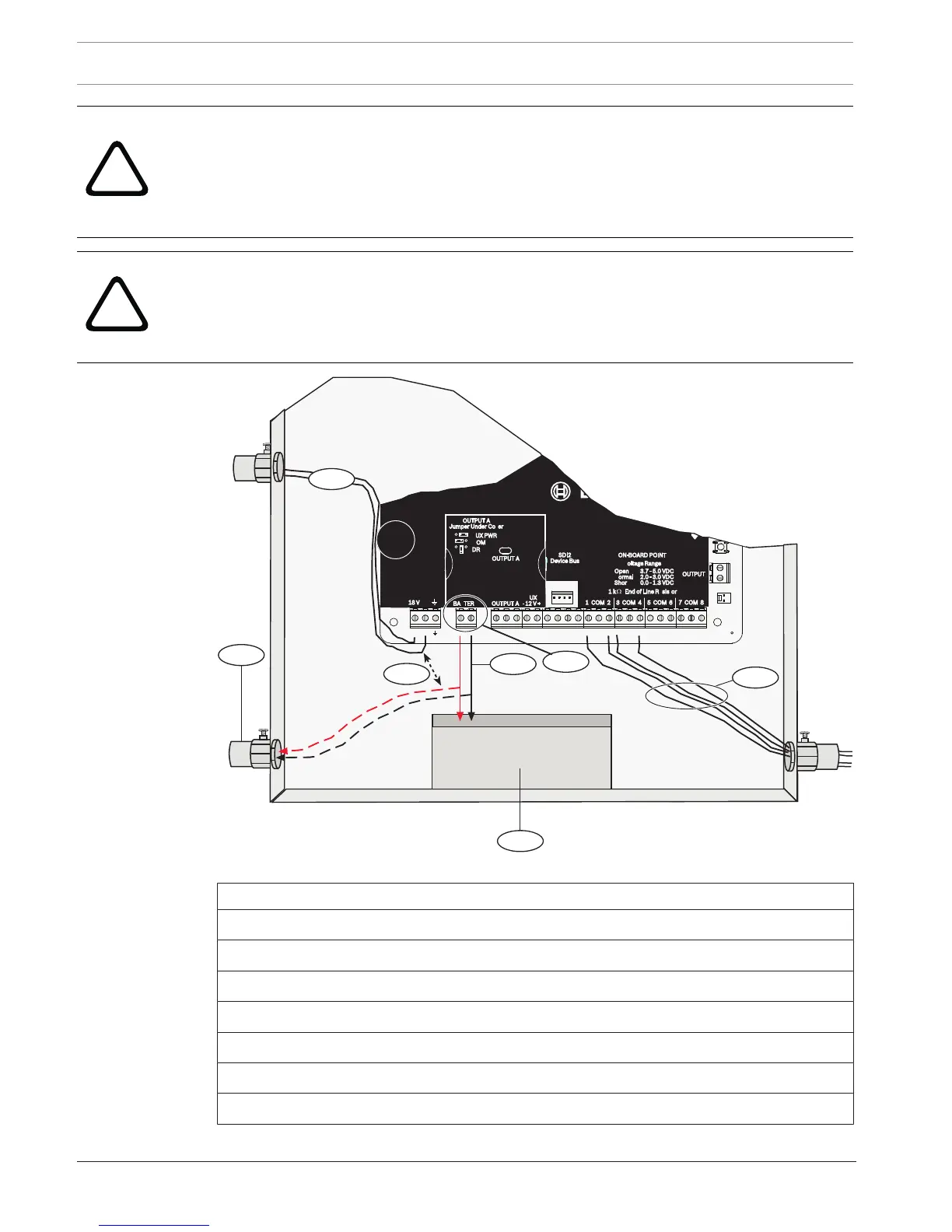
Figure6.1: Non-power-limited wiring (B5512 shown)
Callout ᅳ Description
1 ᅳ Conduit required for use with external batteries
2 ᅳ To UL listed class 2 transformer 18 VAC 22 VA 60 Hz
3 ᅳ 0.25 in (6.4 mm) minimum
4 ᅳ Battery terminals. BAT- is non-power limited
5 ᅳ Battery wires
6 ᅳ 12 V sealed lead-acid rechargeable battery (D126/D1218)
7 ᅳ Sensor loop wires
 Loading...


