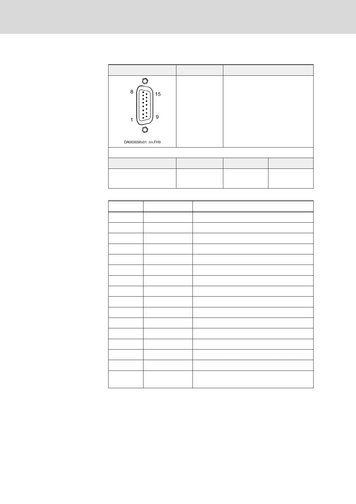
Control X4.Out
View Identification Function
Control
X4.Out
Connection for encoder evaluation
of drive controller
D-Sub 15-pin, male Unit Min. Max.
Connection cable
Stranded wire
mm
2
0,25 0,5
Tab. 8-21: Function, Pin Assignment, Properties
Connection Signal Function
1 GND_shld Connection signal shields (inner shields)
2 A+ Track A analog positive
3 A- Track A analog negative
4 GND_Encoder Reference potential for power supplies
5 B+ Track B analog positive
6 B- Track B analog negative
7 Data_Hall+ Data transmission Hall sensor signal positive
8 Data_Hall- Data transmission Hall sensor signal negative
9 R+ Reference track positive
10 R- Reference track negative
11 +12V Encoder supply 12 V
12 +5V Encoder supply 5V
13 CLK_Hall+ Clock Hall sensor signal positive
14 CLK_Hall- Clock Hall sensor signal negative
15 Sense- Return of reference potential (Sense line)
Connector
housing
Overall shield
Tab. 8-22: Pin Assignment
Bosch Rexroth AG DOK-INDRV*-HCS01******-PR05-EN-P284/341
Rexroth IndraDrive CsDrive Systems with HCS01
Cables, accessories, additional components

 Loading...


