IV. Auxiliary Instruction of Circuit Diagram
1. Instruction of Power Supply and Earth Wire
30: Primary live wire from the battery
30a: Primary live wire from the battery
15: From the ignition switch (IGN1)
15a: From the ignition switch (IGN2)
Ka: From ignition switch (ACC, disconnect at start)
58b(RHEO): power supply for noctilucence illumination
30–(GROUND): Earth wire, from cathode terminal of the battery
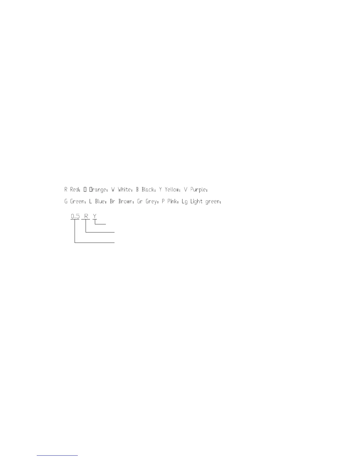
2. Wire Size and Color
Secondary color
Primary color
Lead wire size(mm)
3. Definition of Main Controls
This circuit control theory diagram uses “instrument plug/” to indicate the integrated relay plug of
the instrument electric box.
This circuit control theory diagram uses “ECU” to indicate the engine control unit.
This circuit control theory diagram uses “BCM” to indicate the body control module.
4. Pin Definition Explanation
The pin definition explanation of the circuit theory diagram:
For instance as follows:
4.1.