Cabling the Switch Processor Input/Output Line Card
▄ ASR 5000 Installation Guide
T1 3-Pin BITS Interface Version
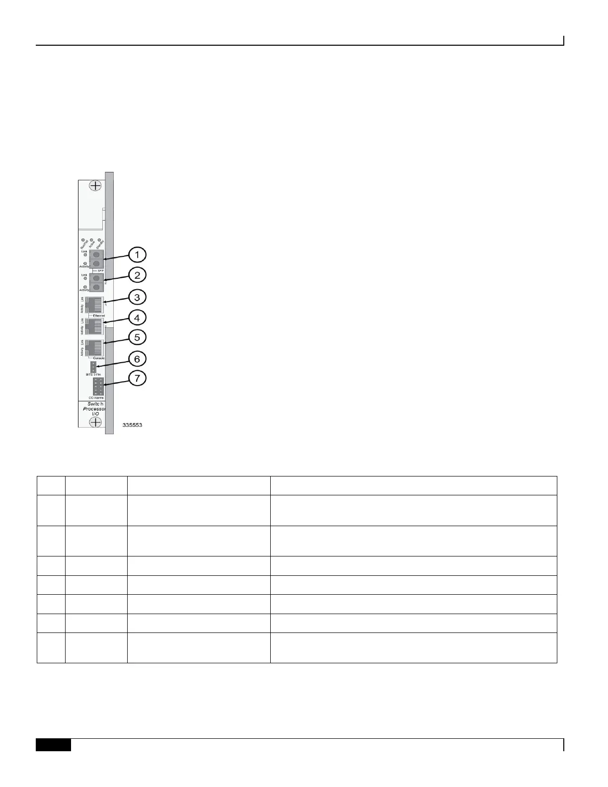
The figure and table that follow provide information on the various interfaces in this version of the SPIO.
Figure 29. SPIO BITS 3-Pin Interface Callouts
Table 31. SPIO 3-Pin BITS Interface Descriptions
Optical fiber, Small Form-factor
Pluggable
Gigabit Ethernet interface for connecting to management LAN
Optical fiber, Small Form-factor
Pluggable
Gigabit Ethernet interface for connecting to management LAN
10/100/1000 Ethernet for connecting to management LAN
10/100/1000 Ethernet for connecting to management LAN
RS-232 interface for local administration of the system
BITS interface for T1 (DS1) clock source [software selectable]
Isolated dry-contact relay interfaces for connection to Central Office
(CO) alarm monitoring panel
 Loading...


