ASR 5000 Hardware Platform Overview
ASR 5000 Installation Guide ▄
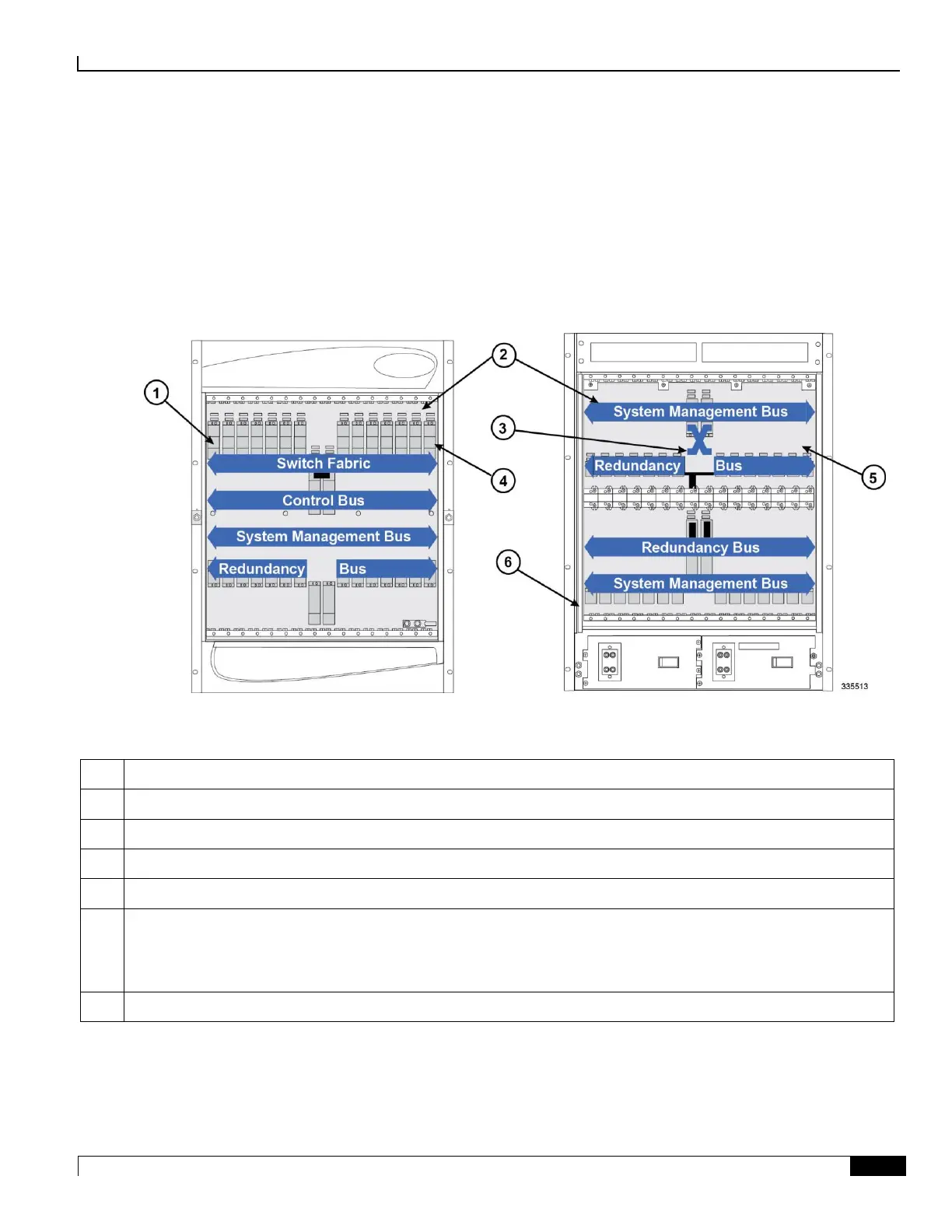
Midplane Architecture
The midplane separates the front and rear chassis slots. The connectors on the midplane provide intra-chassis
communications, power connections, and data transport paths between the various installed cards.
The midplane also contains two independent -48 VDC busses (not shown) that distribute redundant power to each card
within the chassis.
Figure 4. Midplane/Switch Fabric Architecture
Table 4. Midplane and Bus Descriptions
Slot number 1 (left-most application card slot)
Chassis midplane: provides intra-chassis communications and data transport paths between the various installed cards
Chassis slot number 16: right-most application card slot
Chassis slot number 17: upper right-most line card slot. The 10 Gigabit Ethernet Line Card (XGLC) is a full-height line
card that takes up the upper and lower slots in the back of the chassis. Use the upper slot number only when referring to
installed XGLCs. Slot numbering for other half-height lines cards is maintained: 17 to 32 and 33 to 48, regardless of the
number of installed XGLCs.
Chassis slot number 48: lower left-most line card slot

 Loading...


